
Manufacturing apparatus and method for producing a preform

a manufacturing apparatus and preform technology, applied in the direction of turning machines, turning machine accessories, drawing profiling tools, etc., can solve the problems of weak joint types, unlikely to be formed in an automation process, and material used for the production of preforms that does not meet the strength requirements for the final preform, etc., to reduce production time, reduce discontinuities, and improve efficiencies

Inactive Publication Date: 2009-12-17
CENTURY
View PDF96 Cites 12 Cited by
  • Summary
  • Abstract
  • Description
  • Claims
  • Application Information

AI Technical Summary

Benefits of technology

[0011]The spiral joint, and the manner in which the preform is manufactured, creates a consistently strong joint that does not separate during subsequent processing of the preform. The spiral joint eliminates any sharp discontinuities that may arise due to a gap in the preform. Additionally, utilization of the spiral joint lends itself to an automated production setting thereby decreasing production time and increasing efficiencies.

Problems solved by technology

More specifically, the material used for the production of preforms does not meet the strength requirements for the final preform.
However, these joint types are weak and tend to separate during subsequent processing of the preform.
Further, these joint types are complicated and unlikely to be formed in an automation process.

Method used


Image

  • Manufacturing apparatus and method for producing a preform
  • Manufacturing apparatus and method for producing a preform
  • Manufacturing apparatus and method for producing a preform

Examples


Embodiment Construction

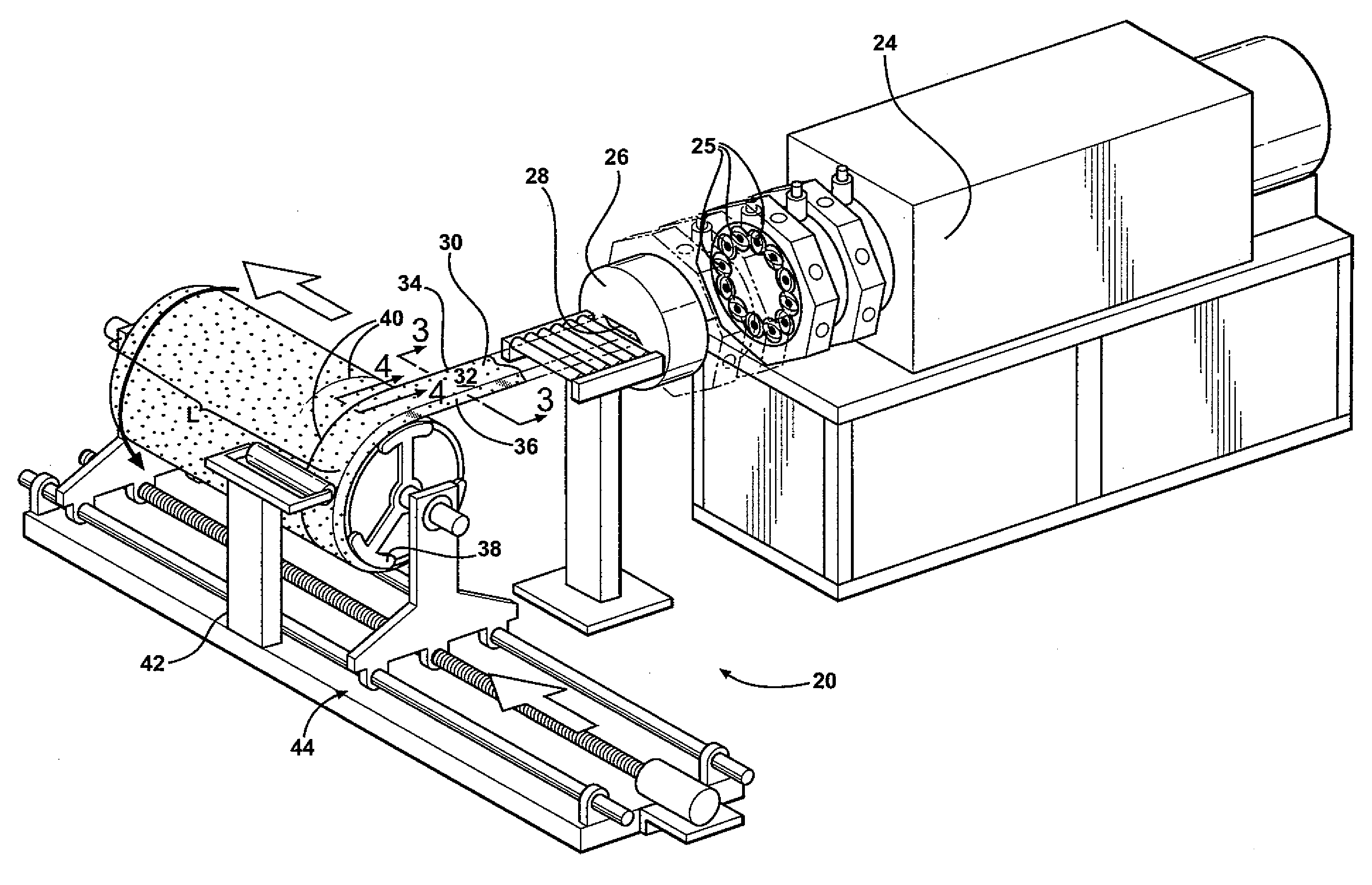
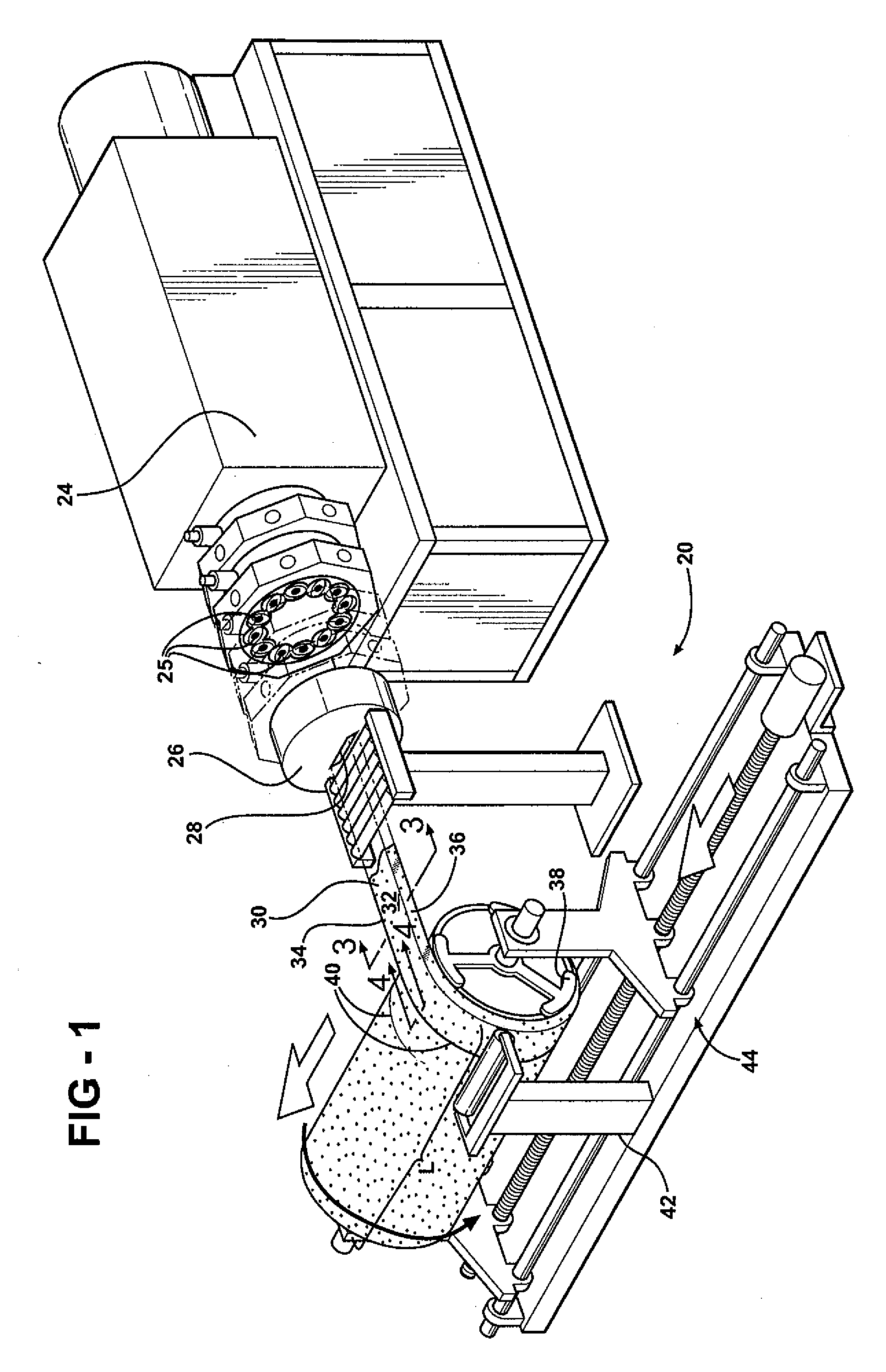
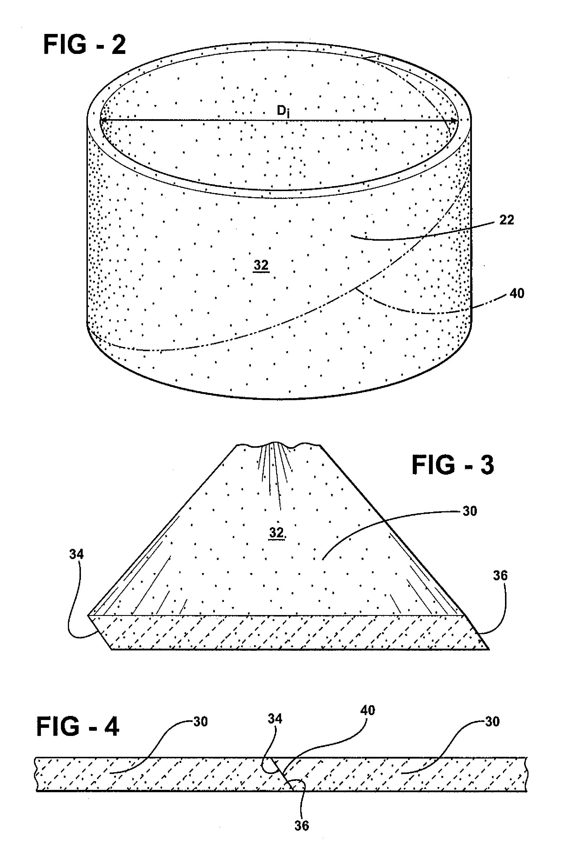
[0019]Referring to the Figures, wherein like numerals indicate like or corresponding parts throughout the several views, a manufacturing apparatus 20 for producing a ceramic article or preform 22 from a material (not shown) is generally shown in FIG. 1. The preform 22 has a width and a final configuration defining an internal diameter Di as shown in FIG. 2.

[0020]The manufacturing apparatus 20 includes a multi-screw extruder 24 for processing the material and producing an extrudate 30. The material preferably includes ceramic particles and ceramic fibers with an aspect ratio of greater than 3:1 with the ceramic fibers being substantially randomly orientated in three dimensions. However, it is to be appreciated that the material can be manufactured from components other than ceramic particles and ceramic fibers without deviating from the broadest scope of the subject invention.

[0021]The multi-screw extruder 24 preferably has at least three intermeshing screws 25. The at least three in...


PUM

PropertyMeasurementUnit
Angular velocityaaaaaaaaaa
Temperatureaaaaaaaaaa
Pressureaaaaaaaaaa

Abstract

The present invention relates to a method of forming a preform from a material having a first edge and a second edge utilizing a mandrel. The method comprises the step of extruding the material through an extruder to form an extrudate. The first edge of the extrudate has a configuration complementary to a configuration of the second edge of the extrudate. The method also includes wrapping the material around the mandrel by abutting the first edge and the second edge to form a spiral joint.The invention uses a manufacturing apparatus comprising a multi-screw extruder having at least three intermeshing screws for forming the extrudate. The mandrel receives the extrudate and a pressure-applying device adjacent to the mandrel engages the extrudate and applies pressure to the spiral joint to create a smooth exterior surface of the extrudate and to define the preform.

Description

RELATED APPLICATIONS[0001]This application claims priority to and all advantages of U.S. Provisional Patent Application No. 61 / 132,281, which was filed on Jun. 17, 2008.BACKGROUND OF THE INVENTION[0002]1. Field of the Invention[0003]The present invention relates to a manufacturing apparatus and a method of producing a preform.[0004]2. Description of the Related Art[0005]Manufacturing preforms, such as ceramic preforms, are known in the industry. However, the current methods of manufacturing ceramic preforms are accomplished through a manual batch mixing process and then a manual formation of the design configuration. Traditionally, preforms in the shape of a cylinder are hand formed from a material. A metal wire is disposed about the preform for strengthening the preform. More specifically, the material used for the production of preforms does not meet the strength requirements for the final preform. As such, the metal wire is required to add strength to the final preform. A preform...

Claims


Application Information

Patent Timeline
IPC IPC(8): B28B21/42B29C48/395B29C48/425
CPCB28B11/245Y10T428/1314B29B7/485B29C47/0004B29C47/0021B29C47/38B29C47/42B29K2105/06C04B35/565C04B35/62204C04B35/6263C04B35/62635C04B35/62655C04B35/6269C04B35/6316C04B35/632C04B35/6365C04B35/638C04B35/806C04B2235/3418C04B2235/3826C04B2235/5228C04B2235/5248C04B2235/526C04B2235/5264C04B2235/5268C04B2235/5296C04B2235/5436C04B2235/6021C04B2235/6562C04B2235/77F16D65/125B29C47/881B29K2909/02B29C47/0059B29C47/0064B29C47/402B29C47/408B28B21/48Y10T428/31678B29C48/08B29C48/12B29C48/13B29C48/022B29C48/91B29C48/9105B29C48/0019B29C48/0021B29C48/395B29C48/402B29C48/425B29C48/435B29C48/9135B29C48/43Y02P40/60C04B35/80C22C29/065F16D69/028
Inventor MCCULLOUGH, THOMAS W.SCHUETZ, JAMES E.ANDERSON, NEILLACOSSE, JUSTINWOOD, THOMAS D.
Owner CENTURY
Learn More