Eureka AIR delivers breakthrough ideas for toughest innovation challenges, trusted by R&D personnel around the world.

Sleeve Steering and Reinforcement

a technology of sleeve steering and reinforcement, which is applied in the direction of medical devices, catheters, other medical devices, etc., can solve the problem of little stiffness of torsion provided by the shim

Inactive Publication Date: 2009-12-10
CATHRX LTD
View PDF12 Cites 39 Cited by
  • Summary
  • Abstract
  • Description
  • Claims
  • Application Information

AI Technical Summary

Benefits of technology

[0046]It is an advantage of the invention that a sleeve steering and reinforcing device 10 is provided which facilitates reinforcing of a sleeve while permitting steering of a distal end of the sleeve and which facilitates transmission of torsion. A further advantage is that the device 10 can be arranged in an electrode sheath of the catheter itself to facilitate steering of a distal end of the electrode sheath of the catheter. This is particularly advantageous when used in conjunction with the Applicant's method of manufacturing an electrode sheath of a catheter as described in the Applicant's International Patent Application No. PCT / AU01 / 01339 dated 19 Oct. 2001 and entitled “An electrical lead”. The contents of that International Application are incorporated in this specification by reference. As described in that specification, the lumen of the electrode sheath is unimpeded by electrode conductors so that the steering wires 26 can be arranged within the lumen while still providing a small diameter electrode sheath. Those skilled in the art will appreciate that the smaller the diameter of an elongate device such as the electrode sheath or an introducer carrying the electrode sheath, the easier it is to steer the elongate device through the vascular system of a patient.

Problems solved by technology

A problem with this arrangement is that there is very little stiffness in torsion provided by the shim.

Method used


Image

  • Sleeve Steering and Reinforcement
  • Sleeve Steering and Reinforcement
  • Sleeve Steering and Reinforcement

Examples


first embodiment

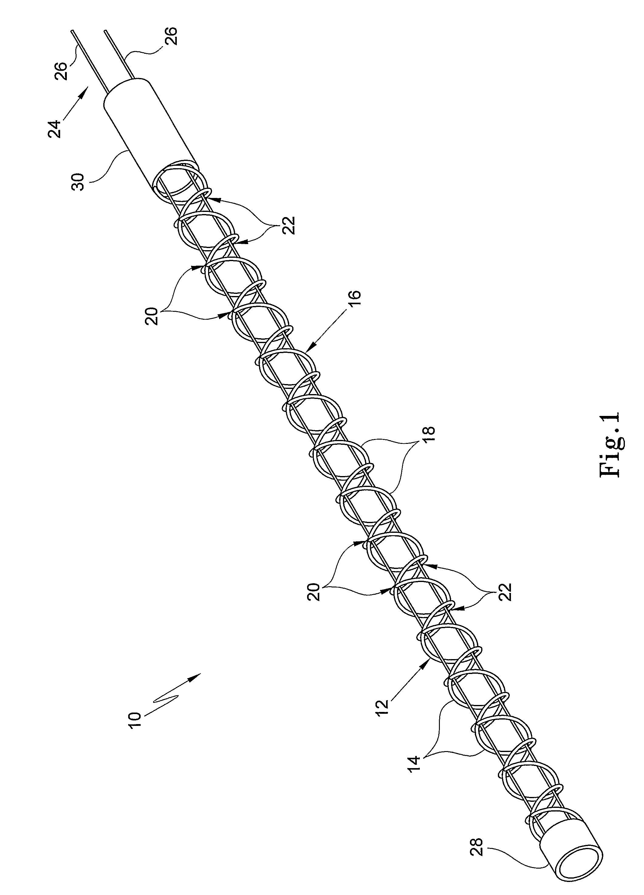
[0029]In FIG. 1 of the drawings, reference numeral 10 generally designates a sleeve steering and reinforcing device, in accordance with the invention. The device 10 includes a first, elongate, helical element 12 having spaced turns 14. The device 10 further includes a second, elongate, helical element 16, once again, having spaced turns 18. The first element 12 and the second element 16 are co-axially arranged in register with each other. The turns 14 of the first helical element 12 are oppositely directed with respect to the turns 18 of the second helical element 16 to provide coinciding zones of intersection 20 and 22.

[0030]In the embodiment shown in FIG. 1 of the drawings, the pitch of the turns 14 of the helical element 12 is the same as the pitch of the turns 18 of the helical element 16.

[0031]The turns 14, 18 of the helical element 12, 16, respectively, coincide at the zones 20 and 22. The zones 20 are arranged along a longitudinally extending, imaginary line. Similarly, the z...

second embodiment

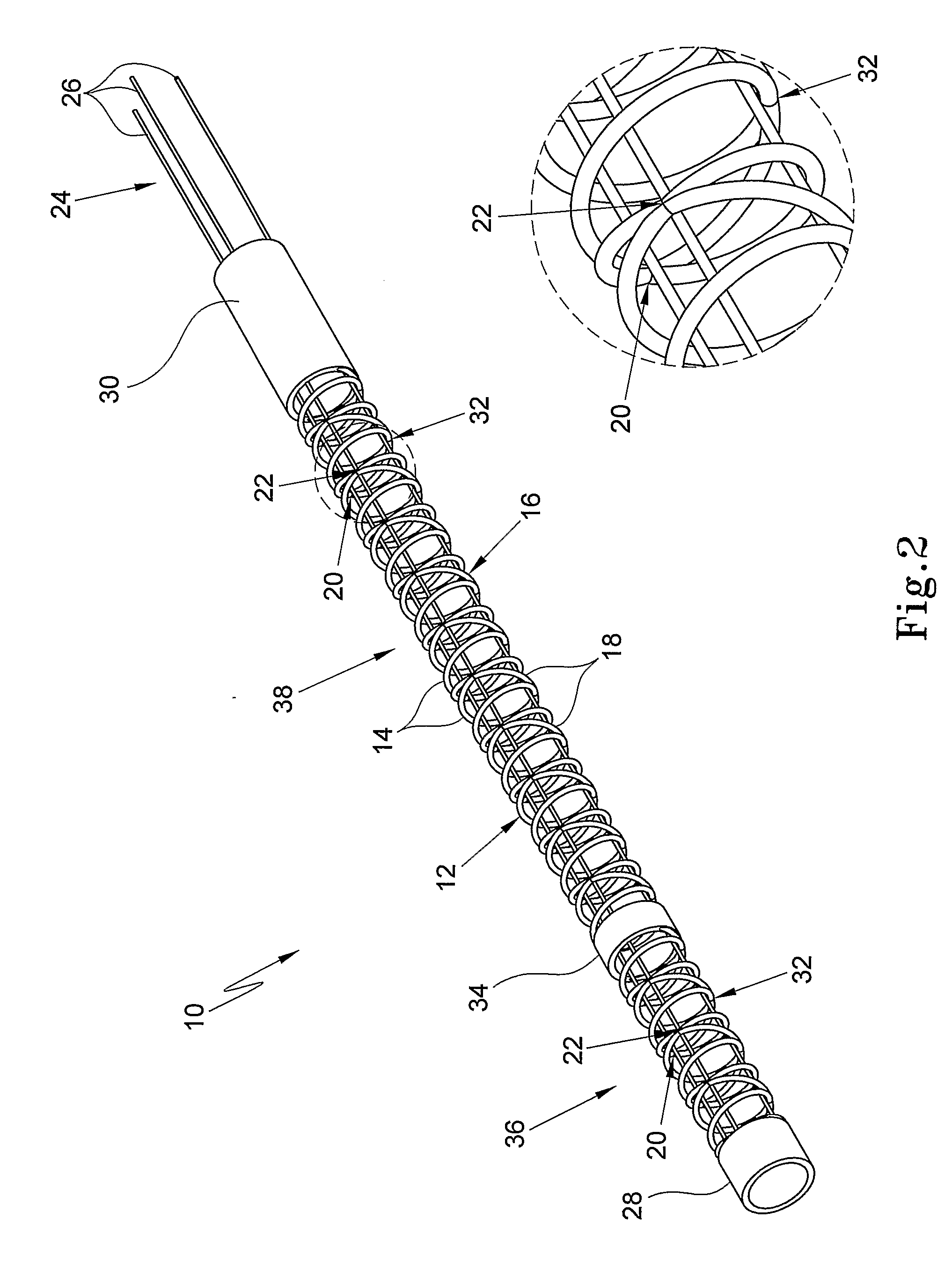
[0036]Referring now to FIGS. 2 to 4 of the drawings, a sleeve steering and reinforcing device 10 is described. With reference to FIG. 1 of the drawings, like reference numerals refer to like parts, unless otherwise specified.

[0037]Once again, the device 10 comprises two co-axially arranged elongate, helical elements 12, 16 with oppositely directed turns 14 and 18, respectively. However, in this embodiment, the pitch of the turns 14 of the helical element 12 is half that of the pitch of the turns 18 of the helical element 16. As a result, the turns 14 and 18 intersect at three zones 20, 22 and 32. Once again, the zones 20 are arranged along a first imaginary line, the zones 22 are arranged along a second, parallel, imaginary line and the zones 32 are arranged along a third, parallel, imaginary line. These imaginary lines are spaced from each other by 120°.

[0038]In this embodiment, the control arrangement 24 comprises at least three control wires 26. By appropriate manipulation of any...


PUM


Abstract

A sleeve steering and reinforcing device (10) includes a first, elongate, helical element (12) having spaced turns (14). At least one further, elongate, helical element (16) is co-axially arranged with the first helical element (12). The at least one further helical element (16) has a plurality of spaced turns (18) wound in an opposite direction to the turns (14) of the first helical element (12) such that the turns (14, 18) of the elements (12, 16) coincide at predetermined zones (20, 22), the zones (20, 22) being arranged along lines extending parallel to a longitudinal axis of the elements.

Description

CROSS-REFERENCE TO RELATED APPLICATIONS[0001]The present application claims priority from United States of America Provisional Patent Application No. 60 / 692,848 filed on 20 Jun. 2005, the contents of which are incorporated herein by reference.FIELD OF THE INVENTION[0002]This invention relates to sleeve steering and reinforcement More particularly, the invention relates to a sleeve steering and reinforcing device and to a sleeve including such a device.BACKGROUND TO THE INVENTION[0003]In the use of catheters, a catheter is inserted into a patient's body via an introducer. The introducer or catheter is inserted into the vascular system of the patient's body and is steered to the desired site of the patient's body. At the site, a distal part of the catheter is urged out of the introducer to enable the required therapeutic action, be it diagnosis or treatment, to be taken by the clinician using the catheter.[0004]To enable the clinician to steer the introducer to the desired site, at le...

Claims


Application Information

Patent Timeline
IPC IPC(8): A61M25/092A61M25/00
CPCA61M25/0105A61M25/0147A61M25/0144A61M25/0138
Inventor MILIJASEVIC, ZORANBOOTH, NORMAN
Owner CATHRX LTD
Why Eureka
Eureka Blog
Learn More