Optical recording head, magneto-optical recording head and optical recording apparatus

Inactive Publication Date: 2009-12-10
KONICA MINOLTA OPTO
View PDF5 Cites 21 Cited by
  • Summary
  • Abstract
  • Description
  • Claims
  • Application Information

AI Technical Summary

Benefits of technology

[0012]The object of the present invention is to solve the aforementioned problems and to provide an optical recording head, magneto-optical recording head, optical recording apparatus, and optical recording apparatus using the magneto-optical recording head characterized by a simple structure and slim configuration; and sufficient efficiency even for a light source with smaller output in the case of a plasmon probe used.Means for Solving the Object
[0062]In the present invention, an optical recording head has an optical waveguide mounted on a slider capable of relative movement with respect to a recording medium. This optical waveguide has a light emission angle not perpendicular to the surface, of the slider, opposed to the surface of the recording medium. The incident light from a light source section is guided and is applied to the surface of the recording medium. Therefore, by tilting the light emitting surface of the waveguide, the input end of the waveguide can be positioned on any of the surfaces other than the surface opposed to the surface of the recording medium of the slider. This arrangement allows a fiber to be connected to the waveguide without increase in the head height and to be connected only with a very small space provided. Further, when a plasmon probe is arranged on the light emitting surface of the optical waveguide, the oblique incident light is applied to the plasmon probe, whereby the amplification of light is further increased.

Problems solved by technology

This makes it difficult to downsize the pickup device.

Method used


Image

  • Optical recording head, magneto-optical recording head and optical recording apparatus
  • Optical recording head, magneto-optical recording head and optical recording apparatus
  • Optical recording head, magneto-optical recording head and optical recording apparatus

Examples


Embodiment Construction

[0100]Referring to the drawings, the following describes a light-assisted magnetic recording head, of the present invention, which is an optical recording head provided with a magnetic recording element thereon, and an optical recording apparatus equipped therewith. The same portions which are the same or correspondent in the embodiments are assigned the same reference numerals, and the duplicated descriptions will be omitted in some cases.

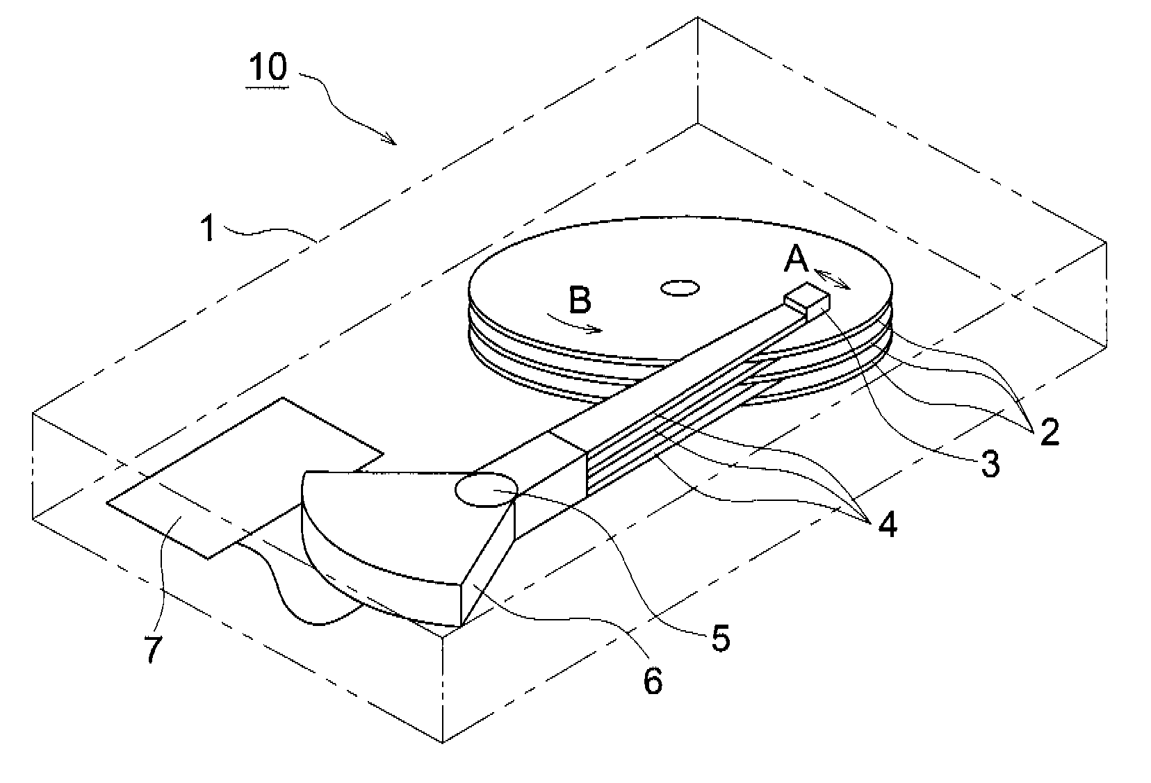
[0101]FIG. 1 shows an example of the schematic structure of a light-assisted magnetic recording apparatus (e.g. hard disk apparatus). This optical recording apparatus 10 includes in an enclosure 1: a recording disk 2 (magnetic recording medium), a suspension 4 supported by a spindle 5 as a fulcrum rotatably in the direction of arrow A (tracking direction), a tracking actuator 6 mounted on the suspension 4, a light-assisted magnetic recording head 3 (hereinafter referred to as magneto-optical recording head 3) mounted on an end of the suspension 4,...


PUM


Abstract

An optical recording head simply structured, enabling a reduction in thickness, and having sufficient efficiency even if a light source with small output is used when a plasmon probe is used. The optical recording head includes a light source section for emitting light, a slider moving relative to a recording medium, and an optical waveguide disposed in the slider, guiding the light from the light source section and irradiating the surface of the recording medium with the light, and having a light emission angle not perpendicular to the surface, of the slider, facing the surface of the recording medium.

Description

TECHNICAL FIELD[0001]The present invention relates to an optical recording head, magneto-optical recording head and optical recording apparatus.BACKGROUND ART[0002]In the magnetic recording system with a higher recording density, the magnetic bit is seriously affected by the external temperature and others. This requires use of a recording medium having a high coercive force. Use of such a recording medium leads to an increase in the magnetic field required for recording. The magnetic field generated by the recording head has an upper limit determined by the saturation magnetic flux density. This saturation magnetic flux density has already come very close to the limit on a material basis, and a drastic increase cannot be expected. To address this problem, proposed is a method in which magnetic weakening is caused by local heating at the time of recording to reduce the coercive force, and the recording is performed when the coercive force is reduced, after that, heating is terminate...

Claims


Application Information

Patent Timeline
IPC IPC(8): G11B7/135
CPCB82Y10/00G11B5/02G11B7/08576G11B7/1384G11B2005/0021G11B11/10536G11B11/10554G11B11/1058G11B2005/0005G11B7/1387G11B5/4866
Inventor KUISEKO, MANAMIUEDA, HIROAKINISHIDA, NAOKIKONNO, KENJISEKINE, KOUJIROUOKITSU, MASAHIROHATANO, HIROSHI
Owner KONICA MINOLTA OPTO
Why Eureka
Try Eureka