Liquid Contact Structure, Structure for Controlling Movement of Liquid and Method of Controlling Movement of Liquid

a liquid contact and liquid technology, applied in the field of liquid contact structure, can solve the problems of limited sensitivity degradation of laser desorption ionization mass spectrometer sensitivity, etc., and achieve the effect of simple configuration

Inactive Publication Date: 2009-12-10
NEC CORP
View PDF1 Cites 4 Cited by
  • Summary
  • Abstract
  • Description
  • Claims
  • Application Information

AI Technical Summary

Benefits of technology

[0017]The convex structures that are formed increase the area of the surface, measured per projected area, of the region in which the convex structures are formed because the area of the side surfaces of the convex structures is added to the area of the surface. The surface area multiplication factor indicates the rate of the increase in the area of the surface that is measured per unit of the projected area. Since the base plate that forms the convex structures has a surface that is lyophilic with respect to the predetermined liquid, the lyophilicity is further increased due to the increase in the area of the surface. When a liquid is dried and decreases in volume, the liquid shrinks while moving toward a high lyophilic area, i.e., toward an area having a high surface area multiplication factor. Since the surface is formed to have the highest lyophilicity within the predetermined region, the liquid is finally concentrated in this region. Alternatively, since the surface is formed to have the highest lyophilicity within a region which surrounds the predetermined region and which is adjacent to the predetermined region, the liquid is finally concentrated in this region. Thus, effective concentration of a liquid can be achieved in a simple configuration.
[0024]As described above, according to the present invention, a technique for evaporating a liquid while controlling the position and movement thereof on the face of the liquid contact structure, wherein the technique requires no coating and has a simple configuration, can be provided.

Problems solved by technology

This may degrade the sensitivity of the laser desorption ionization mass spectrometer.
As a result, a decrease in sensitivity of the laser desorption ionization mass spectrometer can be limited.

Method used


Image

  • Liquid Contact Structure, Structure for Controlling Movement of Liquid and Method of Controlling Movement of Liquid
  • Liquid Contact Structure, Structure for Controlling Movement of Liquid and Method of Controlling Movement of Liquid
  • Liquid Contact Structure, Structure for Controlling Movement of Liquid and Method of Controlling Movement of Liquid

Examples


first exemplary embodiment

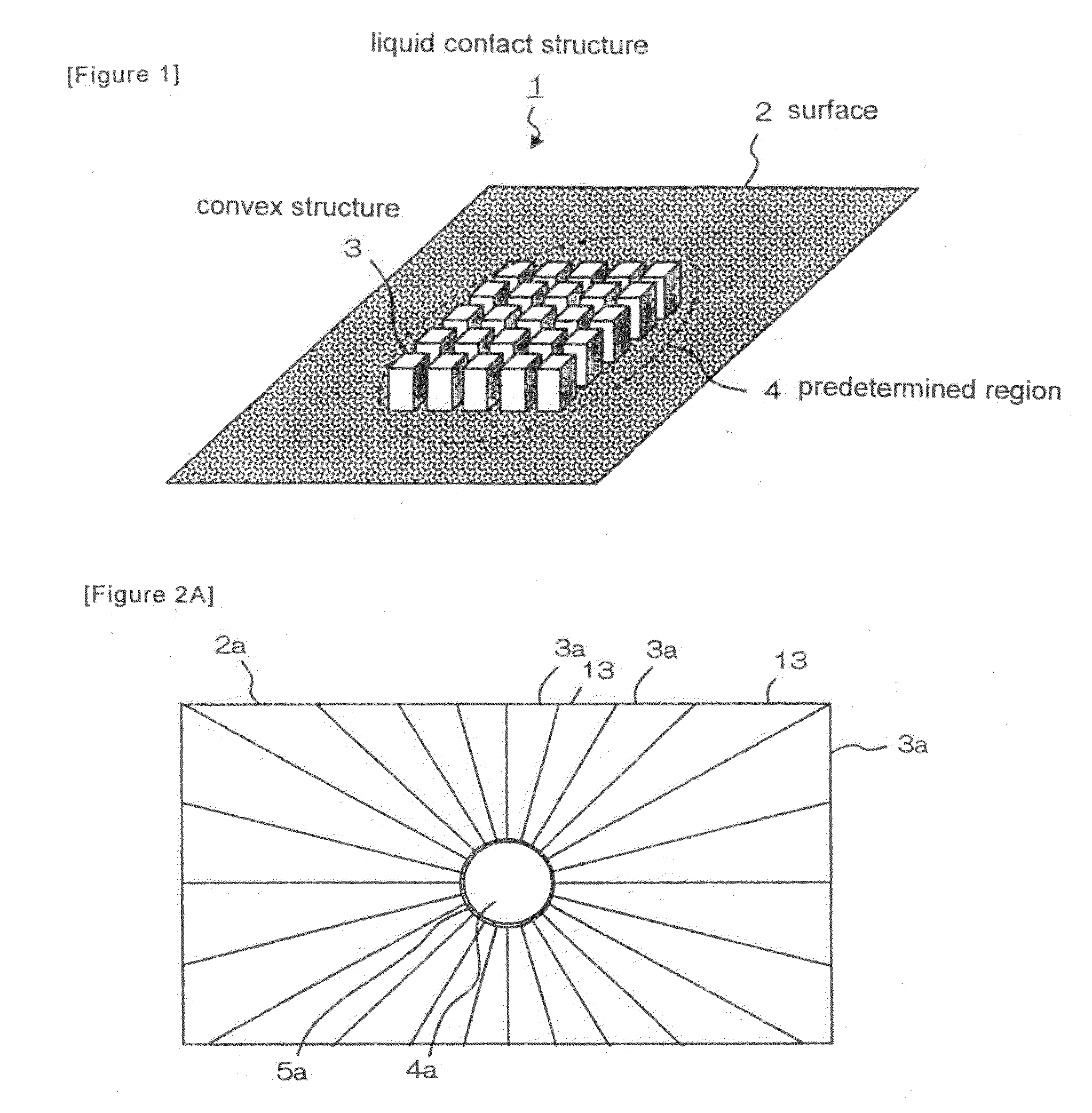
[0050]FIG. 1 is a schematic perspective view of a liquid contact structure according to a first exemplary embodiment of the present invention. Liquid contact structure 1 is a bottom structure of a liquid storage portion (not shown) on a target plate of a mass spectrometer. The base plate (not shown) of liquid contact structure 1 has lyophilic surface 2 which is provided with a plurality of convex structures 3 and which is adapted to come into contact with a liquid. The area of the surface, measured per unit of the projected area, of a region in which convex structures 3 are formed increases by the area of the side surfaces of convex structures 3 that is added, as compared with an area which would be obtained if the region was flat. The ratio of the increase in the area of the surface is referred to as a “surface area multiplication factor.” The surface area multiplication factor is defined as a value which is obtained by dividing an increase in the area of the surface, which is obta...

second exemplary embodiment

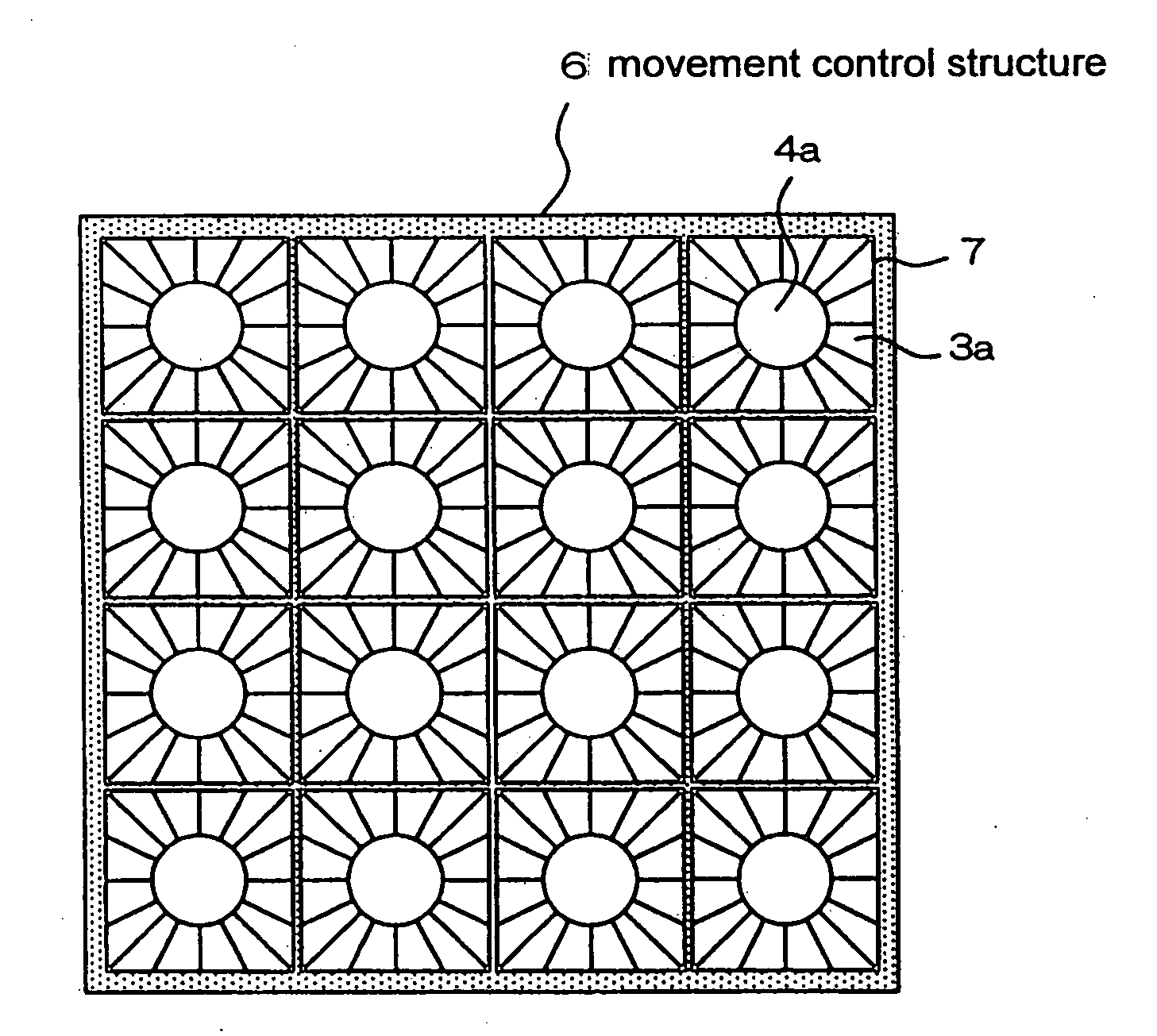
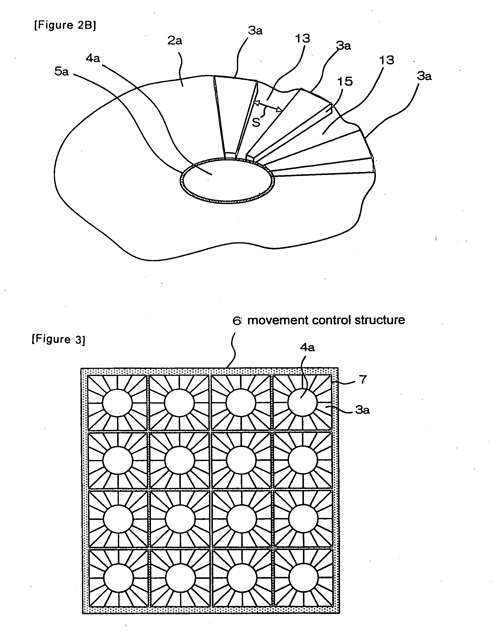
[0057]FIG. 2A is a plan view illustrating a liquid contact structure according to a second exemplary embodiment. FIG. 2B is a perspective view of the liquid contact structure partially illustrating the convex structures. Many fan-shaped convex structures 3a having certain heights are provided on surface 2a. Being spaced apart from each other, convex structures 3a radially extend toward predetermined circular region 4a that is located on the central portion of the base plate. The regions located between convex structures 3a are flat portions 13. This arrangement can be obtained by etching a base plate made of glass based on the fine processing technique for semiconductors. Embossing, press working and machining may also be used depending on the materials. Surface 2a that includes convex structures 3a is lyophilic, similar to the first exemplary embodiment. Surface 2a may also have a coating mentioned above in order to inhibit adsorption of protein etc.

[0058]Also, in the present exemp...

third exemplary embodiment

[0062]FIG. 4 is a plan view illustrating part of a channel for a sample analyzing chip. Channel 9 is formed on chip 8. Convex structures 3b having column shapes, similar to the ones illustrated in the first exemplary embodiment, are formed on the bottom surface of channel 9. Convex structures 3b are arranged such that the density thereof increases stepwise as it becomes closer to predetermined region 4b. Convex structures 3 having the largest density are arranged within predetermined region 4b. Accordingly, the surface within predetermined region 4b has a larger surface area multiplication factor than the surfaces in the regions in the vicinity of predetermined region 4b, and the surface within predetermined region 4b also has the highest lyophilicity. Such convex structure groups 14 are arranged on chip 8 along the longitudinal direction of channel 9.

[0063]In the figure, peripheral region 5b, in which convex structures 3b having smaller density are arranged is provided outside pred...


PUM


Abstract

Liquid contact structure 1 includes lyophilic surface 2 which is provided with a plurality of convex structures 3 and which is adapted to come into contact with a predetermined liquid. Surface 2 has lyophilicity that varies depending on regions of 2 surface according to a difference in a surface area multiplication factor which is caused by convex structures 3, wherein surface 2 is formed to have highest lyophilicity within predetermined region 4 on surface 2.

Description

TECHNICAL FIELD[0001]The present invention relates to a liquid contact structure, a structure for controlling movement of liquid and a method for controlling movement of liquid, and particularly to a liquid contact structure for concentrating a sample on a target plate of a mass spectrometer.BACKGROUND ART[0002]A matrix-assisted laser desorption ionization mass spectrometer has been widely used for the measurement of molecular weight of protein or peptide. When a sample that includes protein or peptide is measured by the spectrometer, crystals of a reagent for promoting ionization, which is called a matrix, are formed, together with the sample, in a predetermined well that is arranged on the target plate.[0003]Various methods for forming crystals have been known. According to one method, a solution that includes a sample is first dripped onto a well and then a solution in which a reagent for promoting ionization called a matrix is dissolved is dripped thereon. As the solvent of the ...

Claims


Application Information

Patent Timeline
IPC IPC(8): G01N1/28G01N27/62
CPCB01L3/502746B01L3/5088B01L2300/0819B01L2300/0864B01L2300/089H01J49/0418B01L2400/0406B01L2400/086G01N1/42G01N27/447B01L2300/165
Inventor HATTORI, WATARUKAWAURA, HISAO
Owner NEC CORP
Why Eureka
Try Eureka