Correlated Magnetic Coupling Device and Method for Using the Correlated Coupling Device

a technology of correlated magnetic coupling and correlated coupling device, which is applied in the direction of magnetic bodies, underwater equipment, instruments, etc., can solve the problems of increased dexterity and additional problems on the part of the person

Inactive Publication Date: 2009-12-03
CORRELATED MAGNETICS RES LLC
View PDF46 Cites 5 Cited by
  • Summary
  • Abstract
  • Description
  • Claims
  • Application Information

AI Technical Summary

Benefits of technology

[0005]In one aspect, the present invention provides a coupling device, more specifically but not by way of limitation a coupling device that is integrally mounted into the mateable components of a scuba air delivery system such as but not by way of limitation a first stage regulator, a second stage regulator, an air hose, an air gauge, a dive computer, a buoyancy control device, and a compressed air tank. An exemplary coupling device functioning to operably couple a first stage regulator with a compressed air tank wherein the first stage regulator includes at least one portion that is designed to be operably secured to the compressed air tank having integrated thereon a first magnetic field emission structure where the first magnetic field emission structure interacts with a second magnetic field emission structure that is integrally mounted on the compressed air tank, wherein each of the first and second magnetic field emission structures comprise an array of field emission sources each having positions and polarities relating to a desired spatial force function that corresponds to a relative alignment of the first and second magnetic field emission structures within a field domain. The first stage regulator can be releasably secured to the compressed air tank when the first and second magnetic field emission structures are adjacent one another and have a certain alignment with respect to one another. The first stage regulator can be released from the compressed air tank when the first and second magnetic field emission structures are rotated with respect to one another. This is possible because each field emission source of each array of field emission sources has a corresponding field emission amplitude and vector direction determined in accordance with the desired spatial force function, wherein a separation distance between the first and second magnetic field emission structures and the relative alignment of the first and second magnetic field emission structures creates a spatial force in accordance the desired spatial force function. And, the field domain corresponds to first field emissions from the array of first field emission sources of the first magnetic field emission structure interacting with second field emissions from the array of second field emission sources of the second magnetic field emission structure.

Problems solved by technology

Unfortunately traditional coupling devices used to connect components of existing scuba air delivery systems utilize traditional fastening systems employing threads, spring loaded unions or other known fastening mechanisms which can fail or wear out over time and can require a greater degree of dexterity on the part of the person to use in order to properly assemble the components of a scuba air delivery system.
Additionally, many novices can mount the first stage regulator incorrectly creating additional problems.

Method used


Image

  • Correlated Magnetic Coupling Device and Method for Using the Correlated Coupling Device
  • Correlated Magnetic Coupling Device and Method for Using the Correlated Coupling Device
  • Correlated Magnetic Coupling Device and Method for Using the Correlated Coupling Device

Examples


Embodiment Construction

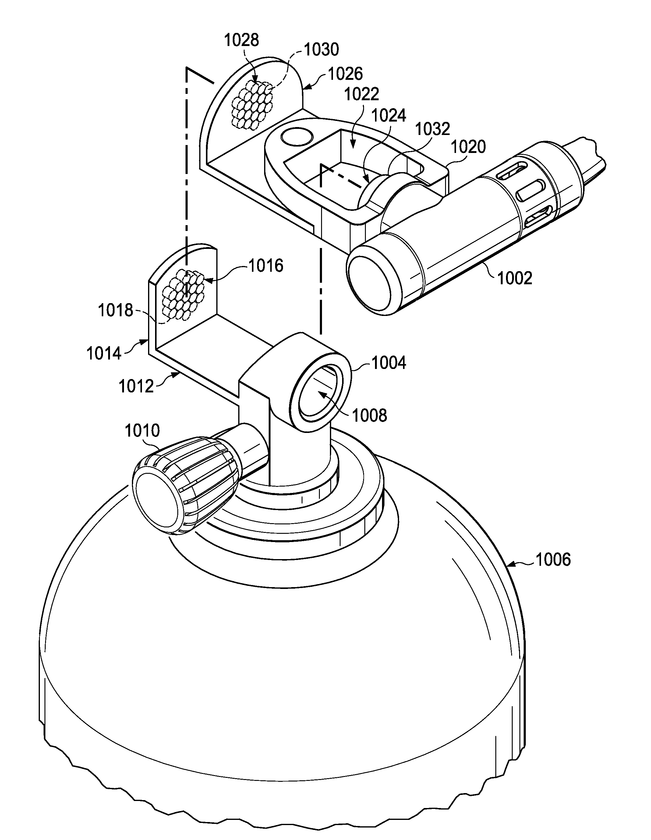
[0020]The present invention includes a coupling device, which utilizes correlated magnetic technology in place of traditional mechanical fasteners to allow a user to easily operably secure components of a compressed gas system, more specifically but not by way of limitation a scuba air system. Utilization of correlated magnetic technology is a significant improvement over convention coupling devices that use threads, clamps or other known fastening devices so an individual can operably couple components of a scuba air system. This significant improvement over the state-of-art is attributable, in part, to the use of an emerging, revolutionary technology that is called correlated magnetics.

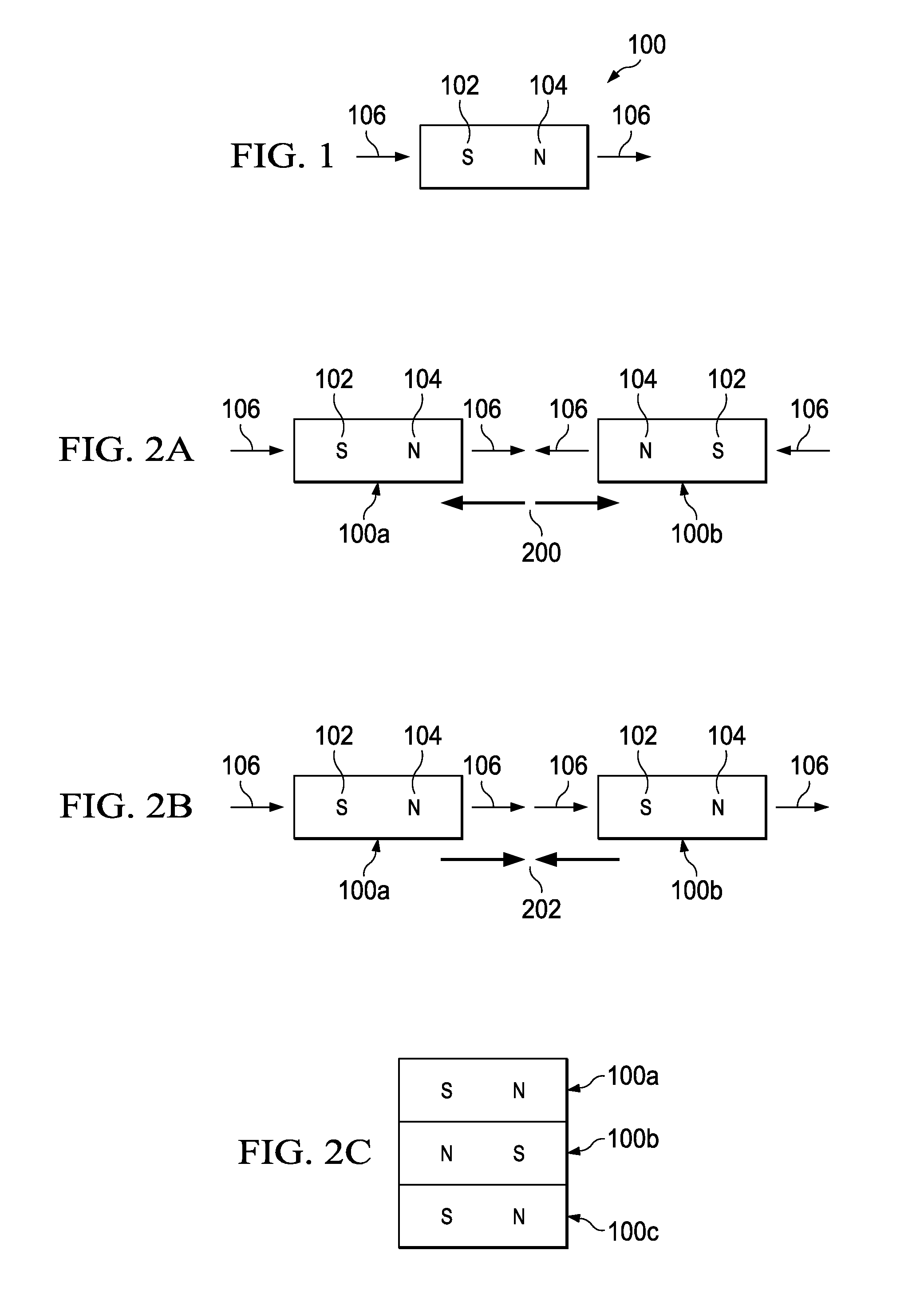
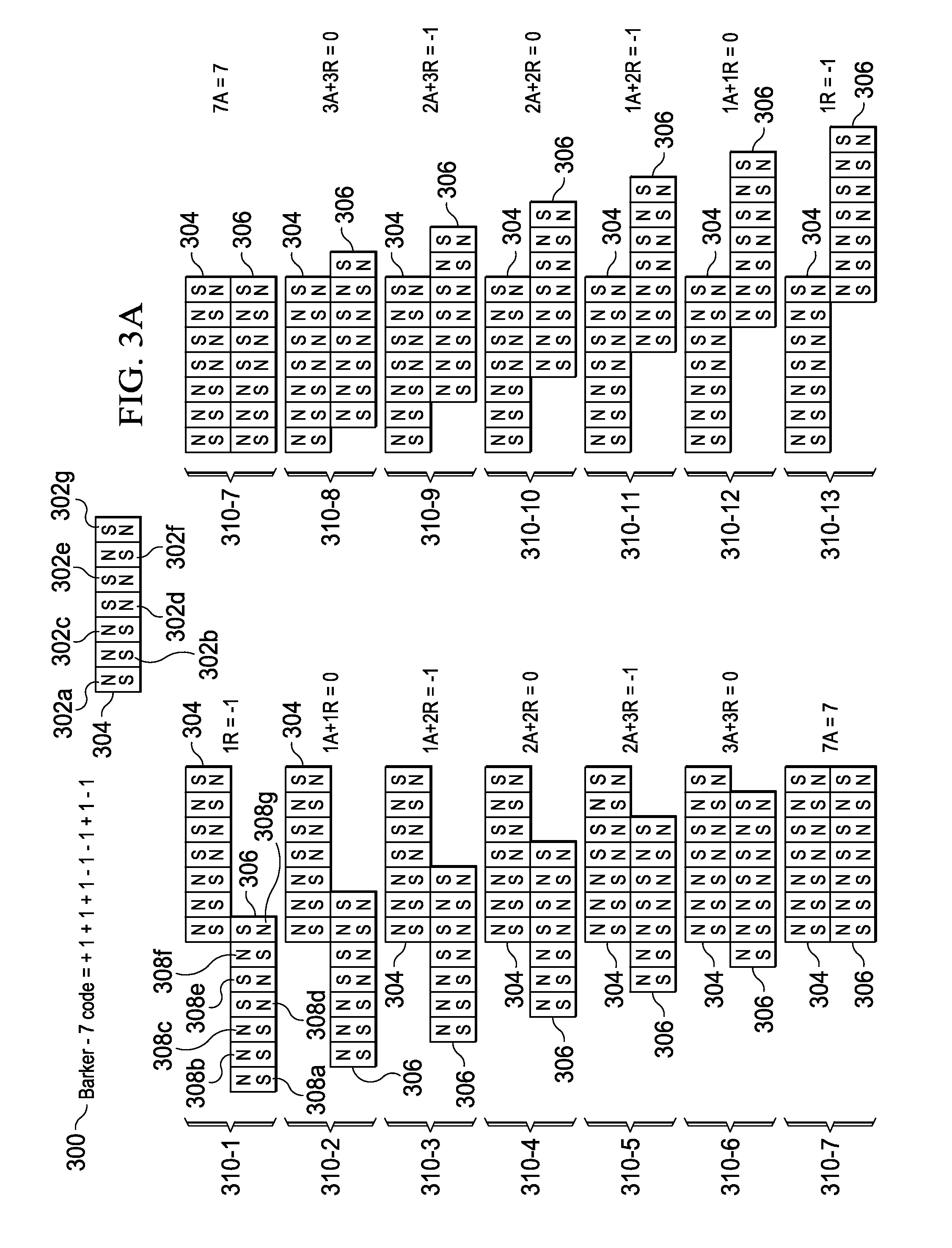
[0021]Correlated magnetics was first fully described and enabled in the co-assigned U.S. patent application Ser. No. 12 / 123,718 filed on May 20, 2008 and entitled “A Field Emission System and Method”. The contents of this document are hereby incorporated herein by reference. A second generation of a...


PUM

PropertyMeasurementUnit
magnetic fieldaaaaaaaaaa
field emission structureaaaaaaaaaa
polaritiesaaaaaaaaaa

Abstract

A compressed gas system component coupling device and method are described herein that use correlated magnets to enable a first component to be secured and removed from the second component. Some examples of components of the compressed gas system include a first stage regulator, a second stage regulator, an air pressure gauge, a dive computer, an air hose, a tank valve and a buoyancy control device. Furthermore the compression force created by the correlated magnets mounted on the first and second components create a hermetic seal therebetween.

Description

CROSS REFERENCE TO RELATED APPLICATION[0001]This application is a continuation-in-part application of U.S. patent application Ser. No. 12 / 476,952 filed on Jun. 2, 2009 and entitled “A Field Emission System and Method”, which is a continuation-in-part application of U.S. patent application Ser. No. 12 / 322,561 filed on Feb. 4, 2009 and entitled “A System and Method for Producing an Electric Pulse”, which is a continuation-in-part application of U.S. patent application Ser. No. 12 / 358,423 filed on Jan. 23, 2009 and entitled “A Field Emission System and Method”, which is a continuation-in-part of U.S. patent application Ser. No. 12 / 123,718 filed on May 20, 2008 and entitled “A Field Emission System and Method”. The contents of these four documents are hereby incorporated herein by reference.TECHNICAL FIELD[0002]The present invention is related to a coupling device that uses correlated magnets enabling a user to easily connect or disconnect one or more components of a compressed gas deli...

Claims


Application Information

Patent Timeline
Patent Type & Authority Applications(United States)
IPC IPC(8): H01F7/02
CPCB63C11/22H01F7/0242G01D18/00
Inventor FULLERTON, LARRY W.ROBERTS, MARK D.
Owner CORRELATED MAGNETICS RES LLC
Why Eureka
Try Eureka