
Process for Forming Pneumatic Tire with Leno Cap Ply

a technology of ply tires and weave caps, which is applied in the field of pneumatic tires, can solve the problems of difficulty in ensuring good adhesion between steel and rubber, difficulty in incorporating steel belts into the tread area of tires, and difficulty in ensuring good adhesion of belts within tires

Active Publication Date: 2009-12-03
MILLIKEN & CO
View PDF14 Cites 20 Cited by
  • Summary
  • Abstract
  • Description
  • Claims
  • Application Information

AI Technical Summary

Benefits of technology

The invention is about a type of tire with a tread, a carcass, and a cap ply. The cap ply is made up of a special type of tape with warp yarns and weft yarns. The second warp yarn is in tension and has a high elongation at break. This tape is placed around the carcass in the area of the belt ply. The technical effect of this invention is to improve the tire's strength and durability.

Problems solved by technology

Technical difficulties have been encountered in incorporating steel belts into the tread area of the tire.
One of the difficulties lies in ensuring good adhesion between the steel and the rubber.
The centrifugal force of the steel belts can cause difficulty in the adhesion of the belt within the tire.
Additionally, movement of the steel belts at higher speeds tends to create excessive temperatures in the tire, which can cause tread failure and delamination.
The problem of delamination is particularly noticeable in the shoulder area of the tire.
However, because this type of overlapping adds weight, the potential length of the overlap is limited.
Additionally, the overlapping section of the fabric causes an uneven thickness of the fabric around the circumference.
However, the longitudinal yarns were positioned in a spaced apart relationship by the rubber of the tape, which does not provide resistance to the separation of the yarns by items that probe at the area between the yarns.

Method used


Image

  • Process for Forming Pneumatic Tire with Leno Cap Ply
  • Process for Forming Pneumatic Tire with Leno Cap Ply
  • Process for Forming Pneumatic Tire with Leno Cap Ply

Examples


Embodiment Construction

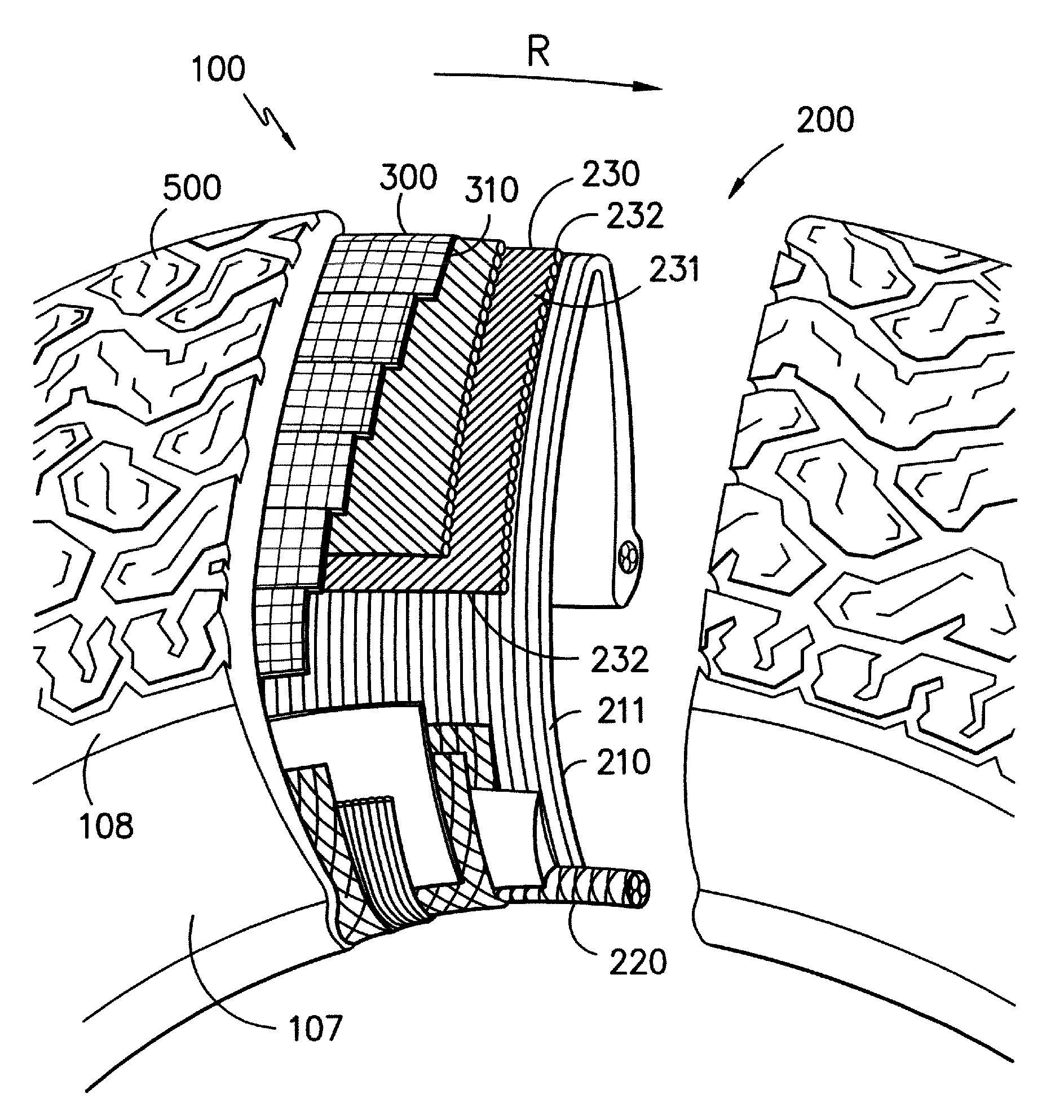
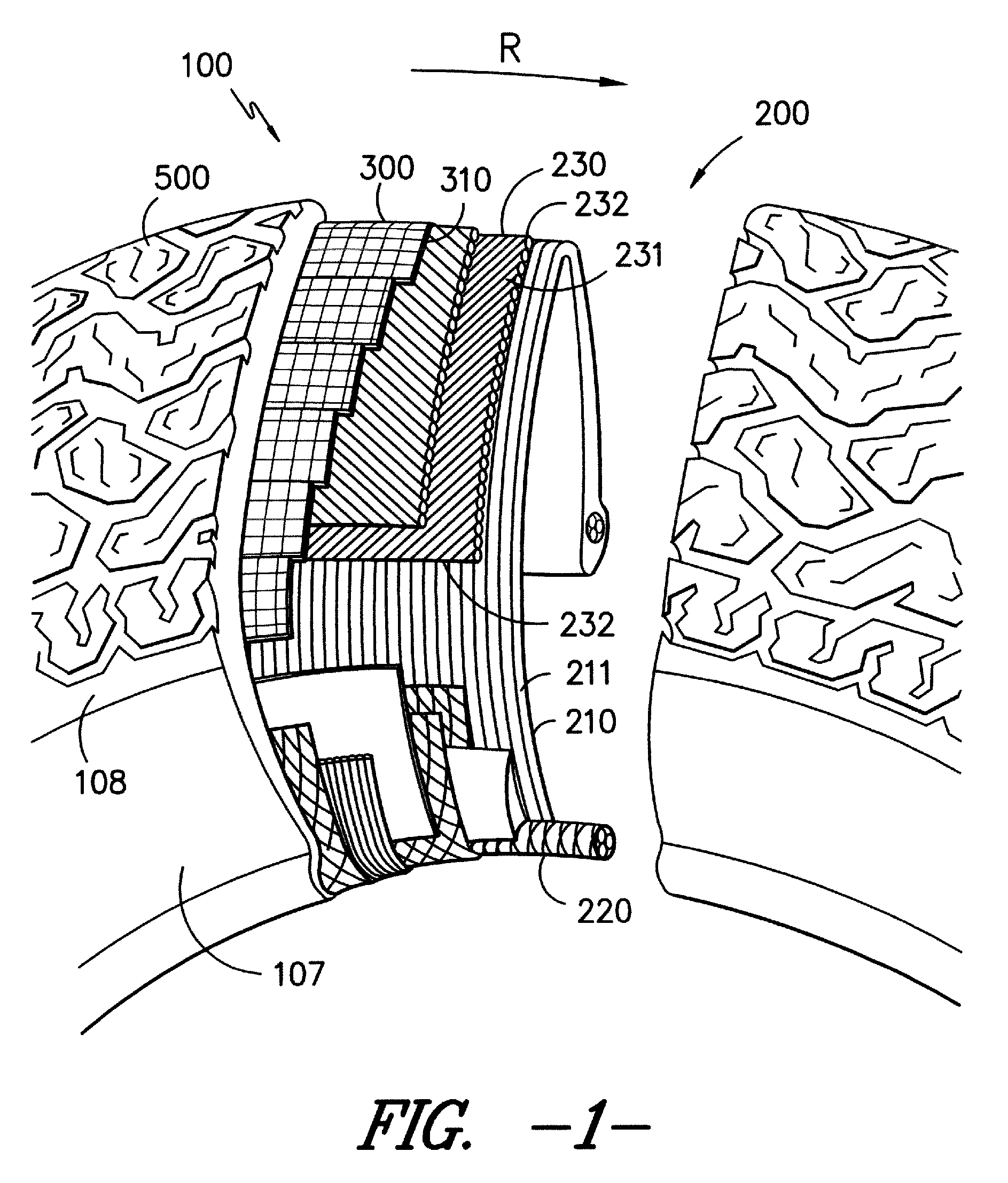
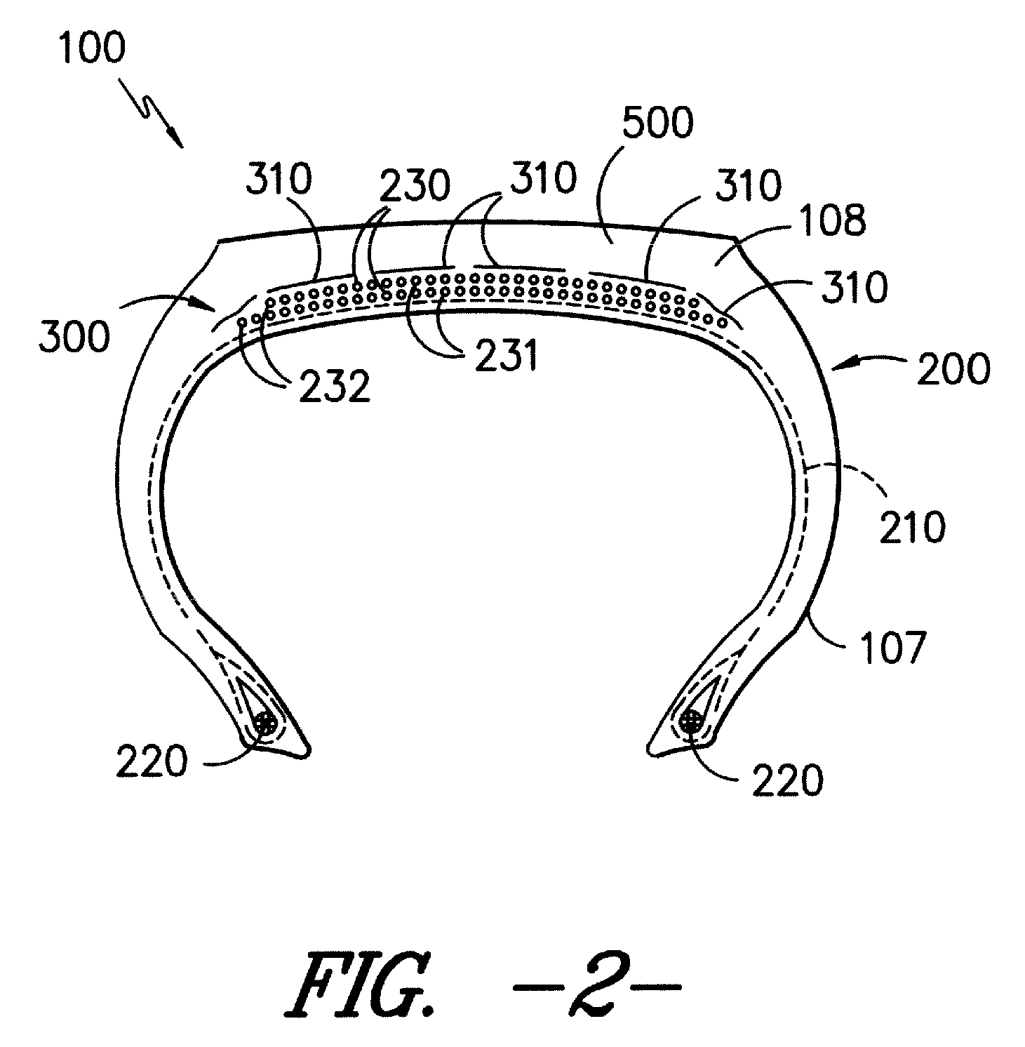
[0018]Referring now to the Figures and in particular to FIGS. 1 and 2, there is shown a tire 100, comprising side walls 107 joined to a tread 500 by shoulders 108. The tire 100 includes a carcass 200 covered by the tread 500. In FIGS. 1 and 2, the tire 100 is a radial tire. However, the present invention is not limited to radial tires and can also be used with other tire constructions. The carcass 200 is formed from one or more plies of tire cord 210 terminating at the inner periphery of the tire in metal beads 220, with at least one belt ply 230 located circumferentially around the 10 tire cord 210 in the area of the tread 500. The tire cord 210 is a rubberized woven fabric having its warps formed from relatively inextensible reinforcing cords 211. In the tire shown in FIG. 1, the carcass 200 is constructed so that the reinforcing cords 211 are running substantially radially of the intended direction of rotation R of the tire 100. The belt plies 230 are formed with relatively inext...


PUM

PropertyMeasurementUnit
elongationaaaaaaaaaa

Abstract

A pneumatic tire containing a tread, a carcass having at least one belt ply disposed below the tread, and a cap ply located between the carcass and the tread. The cap ply comprises at least one layer of an open construction leno weave tape having a pair of warp yarns in the longitudinal direction and a weft yarn in the weft direction. The pair of warp yarns comprises a first warp yarn and a second warp yarn, where the second warp yarn has a force of elongation of between about 1 and 40% the force of elongation of the first warp yarn, where the second warp yarn is in tension, and where the second warp yarn has an elongation at break of greater than 2%. The leno weave tape is disposed in a flat pattern around the circumference of the carcass in the area of the belt ply. A method of making a pneumatic tire is also disclosed.

Description

RELATED APPLICATIONS[0001]This application is a continuation-in-part of co-pending U.S. application Ser. No. 12 / 154,996 filed on May 29, 2008, the contents of which are incorporated by reference herein in their entirety.FIELD OF THE INVENTION[0002]The present invention generally relates to pneumatic tires and in particular to construction of ply tires with leno weave cap plies.BACKGROUND[0003]Typically, tires are manufactured from a single or multiple carcasses of substantially U-shaped sections having metal beads at the inner perimeters of the walls. Support can be provided to a tire carcass by steel cord belt plies extending around the outer periphery of the carcass and across the width of the tread. Such steel belt plies are relatively inextensible in the intended direction of rotation of the tire and include steel belt cords disposed parallel to that direction or at a low angle thereto. The belt plies act to restrict the movement of the tread and give the tire better road-holdin...

Claims


Application Information

Patent Timeline
Patent Type & Authority Applications(United States)
IPC IPC(8): B29D30/08
CPCB29D30/38B29D30/70Y10T152/10765B60C2009/1814Y10T152/10783B60C2009/2261Y10T442/102Y10T442/3179
Inventor MICHIELS, DANY F.PESCHEK, JOHANNDELANOY, WILLYSNAUWAERT, BOUDEWIJN
Owner MILLIKEN & CO
Learn More