Eureka AIR delivers breakthrough ideas for toughest innovation challenges, trusted by R&D personnel around the world.

Resonant circuit and resonant power converter with a narrow operating frequency bandwidth

a resonant power converter and operating frequency bandwidth technology, applied in the field of resonant circuits, can solve the problems of reducing the conversion efficiency of resonant power converters, having to operate in a wider range, etc., and achieve the effect of narrow operating frequency bandwidth and stable voltage outpu

Inactive Publication Date: 2009-11-26
ACBEL POLYTECH INC
View PDF1 Cites 9 Cited by
  • Summary
  • Abstract
  • Description
  • Claims
  • Application Information

AI Technical Summary

Benefits of technology

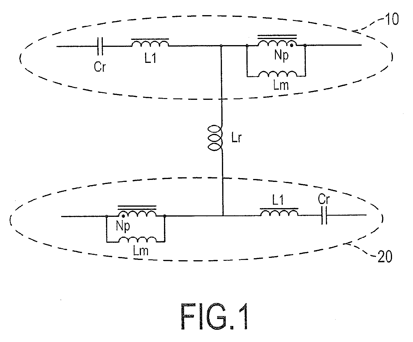
The invention provides a resonant circuit and a resonant power converter with a narrow operating frequency bandwidth that ensures stable voltage output. The resonant circuit includes a series capacitor and a series inductor connected in parallel, and an assistant inductor. The resonant circuit works together with a transforming unit to provide two characteristic resonant frequencies. The resonant power converter includes a square wave generator, a transforming unit, a resonant circuit, a rectifying unit, and a filtering unit. The invention enhances power conversion efficiency and reduces loss by providing a larger range of working voltage to the load at only a relatively smaller operating frequency bandwidth.

Problems solved by technology

An obvious drawback of the LLC circuit is that the resonant power converter has to be operated in a wider operating frequency bandwidth in order to adjust its output voltage.
In cases where a wider operating frequency bandwidth is impossible, it will be difficult for the LLC resonant design to effectively make the conversion or it simply reduces its conversion efficiency.

Method used


Image

  • Resonant circuit and resonant power converter with a narrow operating frequency bandwidth
  • Resonant circuit and resonant power converter with a narrow operating frequency bandwidth
  • Resonant circuit and resonant power converter with a narrow operating frequency bandwidth

Examples


fifth embodiment

[0102]With reference to FIG. 20 for the power converter, the original DC blocking capacitor Cb is replaced by two capacitors Cb1, Cb2 that are connected in series to the two windings Np on the primary side of the transformer unit 40. The positions of the DC blocking capacitors have been mentioned above and can be their other combinations. In particular, putting the DC blocking capacitor on the branch of the assistant inductor Lr results in the smallest current stress.

sixth embodiment

[0103]With reference to FIG. 21 for the power converter, the DC blocking capacitor Cb is replaced by two capacitors Cb1, Cb2. Moreover, the branch of the assistant inductor Lr is connected in series an assistant winding Np′ provided by the transformer unit 40. This configuration does not change the circuit operations, but have different system parameters.

seventh embodiment

[0104]With reference to FIG. 22 for the power converter, two assistant windings Np′ of the transformer unit 40 are connected in series on the two branches of the series inductor L1 and the series capacitor Cr, respectively. This design has an even large influence in the system parameters.

[0105]With reference to FIG. 23, the power converter in this embodiment is based on the design in FIG. 22. The half bridge topology is replaced by a full bridge topology. Therefore, there are four switches Q1˜Q4. However, the resonant circuit is not changed at all. The DC blocking capacitor Cb is disposed in the middle to connected with the assistant inductor Lr in series.


PUM


Abstract

A resonant circuit has two parallel resonant branches and one assistant inductor connecting the two resonant branches. Each resonant branch has a series capacitor and a series inductor connected in series. The other end of the series inductor is for connecting to a primary side of a transformer unit. The resonant circuit can provide two characteristic resonant frequencies fr and fm, so that a resonant power converter using the resonant circuit has an operating frequency fs that satisfies fs>fr or fm<fs<fr. The combination of the two resonant branches and the assistant inductor can reduce the frequency switch range of the resonant power converter within a specific voltage gain.

Description

BACKGROUND OF THE INVENTION[0001]1. Field of the Invention[0002]The invention relates to a resonant circuit and, in particular, to a resonant circuit used in a power converter.[0003]2. Description of Related Art[0004]With reference to FIG. 24, the U.S. Pat. No. 6,344,979, entitled “LLC series resonant DC-to-DC converter” has disclosed a LLC resonant power converter. The power converter mainly includes a square wave generator 100, a transformer 110, a resonant unit 120, a rectifying unit 130 and a filtering unit 140. The resonant unit 120 is connected between the primary side of the transformer 110 and the output terminal of the square wave generator 100. The rectifying unit is connected to the secondary side of the transformer 110. The filtering unit 140 is connected to the output terminal of the rectifying unit 130 for connecting to a load 150.[0005]The resonant unit 120 has a series capacitor Cr connected with a series inductor Ls in series. Both the series capacitor Cr and the se...

Claims


Application Information

Patent Timeline
Patent Type & Authority Applications(United States)
IPC IPC(8): H02M3/335H03H7/01
CPCH02M3/337Y02B70/1491H02M2001/0058Y02B70/1433Y02B70/10H02M1/0058H02M3/33573H02M3/33571H02M3/01
Inventor ZHOU, JUNMA, XIAO-LINGUO, BING
Owner ACBEL POLYTECH INC
Why Eureka
Eureka Blog
Learn More