
Device and Method for Producing a Surround Sound

a technology of surround sound and device, applied in the field of surround sound system, can solve the problems of only imprecise localization of the signal source, inability or not desired inability to achieve spatial localization, so as to reduce the complexity of the device, good spatial localization, and good spatial impression

Inactive Publication Date: 2009-11-19
ENTROPIC COMM INC
View PDF3 Cites 8 Cited by
  • Summary
  • Abstract
  • Description
  • Claims
  • Application Information

AI Technical Summary

Benefits of technology

[0025]Achieved with such circuits or signal processing is a good spatial localization for signal components coming from back left / right and, simultaneously, also a good spatial impression for signal components coming centrally from in back. Preferred circuits can be implemented both for monophonic and for stereophonic surround signals, without a detection circuit being necessary for this. As a result, the complexity of the device is reduced and negative influences due to regulation and the time constants thereof are avoided.

Problems solved by technology

This is often not possible or not desired for reasons of space or for visual reasons.
Because, in this case, the right ear and the left ear of a listener receive exactly the same signals, a spatial localization of the signal is not possible and the sound seems to come centrally from in front.
However, this is achieved at the expense of an only imprecise localization of the signal source, because the signal comes from somewhere in back and seems to come generally from several directions.
The drawbacks of these systems are either only one monophonic surround signal can be processed, such that, after the virtualization, a precise spatial localization of the signal is not allowed, or stereophonic surround signals are processed, which allow a spatial localization of a sound from back left or back right.

Method used


Image

  • Device and Method for Producing a Surround Sound
  • Device and Method for Producing a Surround Sound
  • Device and Method for Producing a Surround Sound

Examples


Embodiment Construction

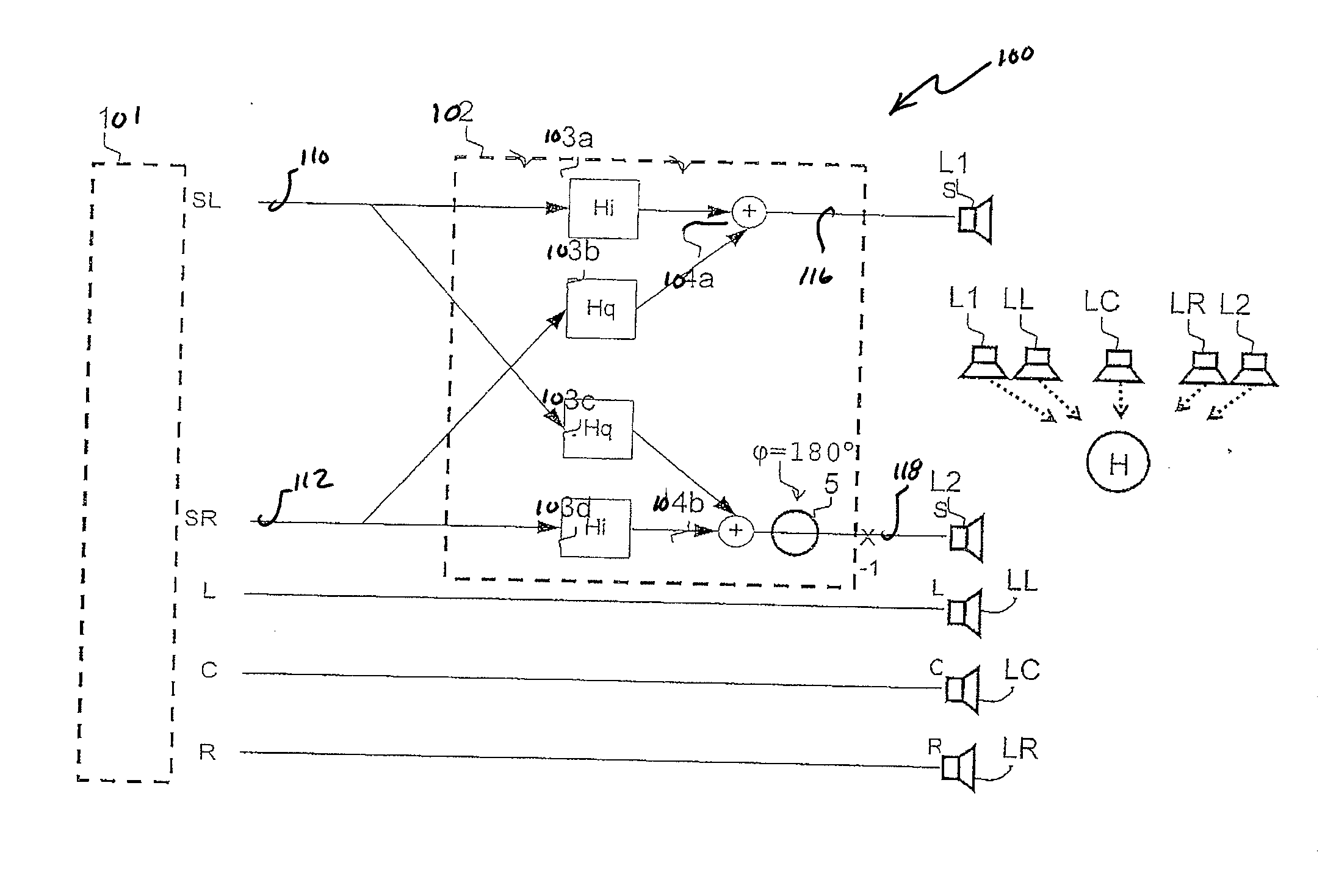
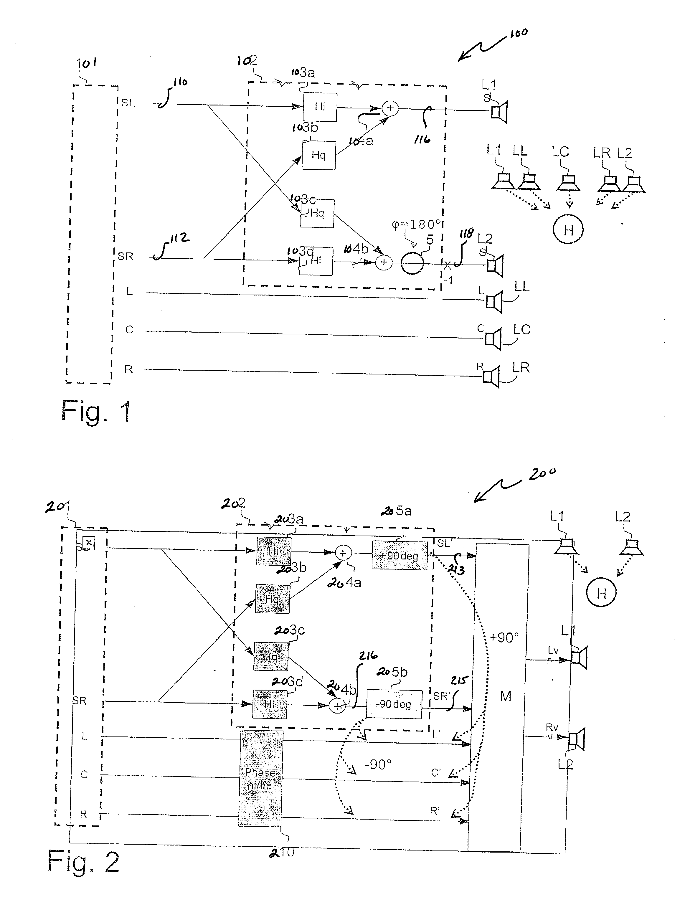
[0037]FIG. 1 illustrates a surround sound system 100, in which a signal source 101, such as, for example, a decoder or a DVD player, provides a first signal SL and a second signal SR, on lines 110, 112 respectively. In this case, the first signal SL is intended for output via a first speaker L1 and the second signal SR for output via a second speaker L2. Applied, however, to the two speakers L1, L2, instead of these signals SL, SR, are a modified first signal SL′ and a modified second signal SR′, so as to produce a surround sound that conveys the impression that, in addition, another signal of the middle signal kind is being output via yet another speaker as a virtual middle speaker.

[0038]The first signal SL on the line 110 is applied to a first multiplication term 103a and the second signal SR on the line 112 is applied to a second multiplication term 103b. The resultant products are summed by summer 104a and the resultant sum is output on line 116 to the first speaker L1. The firs...


PUM


Abstract

A surround sound audio processing system includes a source that supplies a first signal for producing a first sound impression and a second signal for producing a second sound impression. A processing unit modifies the first signal and the second signal to produce a third sound impression of a virtual source, and provides first and second modified signals indicative thereof. The processing unit modifies the first signal and the second signal relative to each other such that the first and second modified signals have a phase shift of between 170° to 190°.

Description

PRIORITY INFORMATION[0001]This patent application claims priority from European patent application 08 009095.4 filed May 16, 2008, which is hereby incorporated by reference.BACKGROUND OF THE INVENTION[0002]The present invention relates to the field of audio systems, and in particular to a surround sound system.[0003]Various systems for producing a surround sound are known. In particular, systems such as the Dolby Digital AC-3®, Dolby ProLogic II®, and DTS® systems, provide signals for front left, front center, front right, back left, and back right, which are connected to speakers that are arranged appropriately in the space surrounding a listener. A subwoofer for low-frequency signals may also be connected. There are also systems, such as, for example, the Dolby Pro Logic® surround sound processing technology that provide only one rear channel, which is arranged in the back center. All of these systems require one or more speakers be located in back of the listener. This is often n...

Claims


Application Information

Patent Timeline
Patent Type & Authority Applications(United States)
IPC IPC(8): H04R5/02
CPCH04S3/02
Inventor VIERTHALER, MATTHIAS
Owner ENTROPIC COMM INC
Learn More