
Data acquisition module and system

Active Publication Date: 2009-11-19
BRUEL & KJAER SOUND & VIBRATION MEASUREMENT
View PDF31 Cites 15 Cited by
  • Summary
  • Abstract
  • Description
  • Claims
  • Application Information

AI Technical Summary

Benefits of technology

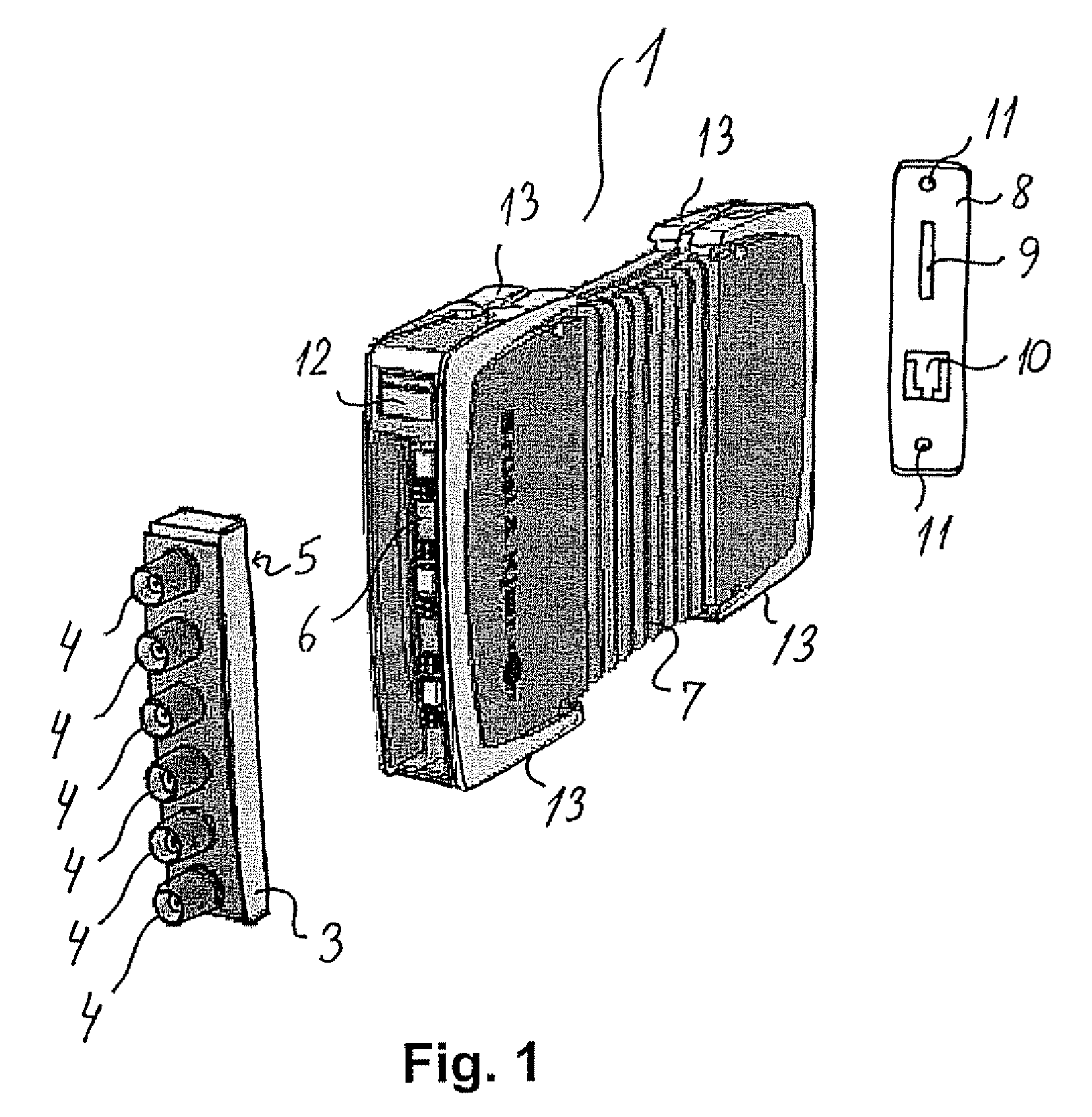
[0008]On the above background it is an object of the present invention to provide a module for data acquisition that can be used as a separate unit for acquisition of data provided by external units such as microphones, accelerometers, strain-gauges, bridge-interfaces or any other electrical transducers, carrying out optional processing of such data and providing said acquired data, or processed versions hereof, to external receptor units, such as computers, analysers, storage means, etc. Furthermore, according to the invention, either one or more of said modules can be mounted together in a frame or rack making it possible for said one or more modules to communicate with each other and / or utilise support functions, such as a power supply, cooling, firmware update or common control functions provided in said frame or rack. The frame provides a compact multi-channel solution.
[0011]The modules according to the invention are furthermore characterised by being provided with output connector means for establishing data / signal communication with external receptor equipment, such as computers, analysers, storage means, etc. According to an advantageous embodiment of the modules of the invention, said output connector means is a LAN connector facilitating direct access to many types of external units, such as personal computers.
[0015]Several important advantages are attained with the modules or system of modules according to the present invention. Thus, the ability to use any module of the invention either in a frame or as a stand-alone module means that it becomes easy to provide a distributed system where the modules can be placed close to the measurement object. A precision time protocol (PTP) makes it possible to synchronise the clocks in the system components with sub-microsecond accuracy. With PoE (Power over Ethernet) via standard LAN cables, the only thing that is needed between modules and a PC are LAN cables and a PoE switch. This minimises the number of cables required in a given setup and results in lower cost, less downtime, easier maintenance and greater flexibility and speed of installation.
[0016]Furthermore, incorporating the detachable front unit as a part of each specific transducer system (and for instance designating the specific front unit used in that system in a clearly recognisable manner, such as by a specific colour) will lead to reduced risk of configuration errors when changing from one specific transducer setup (for instance for performing measurements of sound pressure levels generated by a loudspeaker system in the cabin of an automobile) to another transducer setup (for instance for measuring noise emission (by means of microphones) and vibration (by means of accelerometers) at the engine of the automobile.

Problems solved by technology

A problem with known data acquisition modules and systems is that such modules are provided with a fixed connector configuration for connecting the module to various transducers and / or for providing control signals to external equipment.
Thus, a number of different modules might be necessary in order to carry out different tasks, which is not an optimal solution.
In prior art data modular data acquisition systems, direct data communication between the module and external receptor equipment, for instance a personal computer (PC) is not possible.
A problem with prior art data acquisition modules or units is that they function either as stationary or portable units and that set-ups based on prior art modules often require application of a vast number of cables.
With prior art modules it is also difficult to form distributed data acquisition systems and such modules or units have often limited and predefined options for battery operation.

Method used


Image

  • Data acquisition module and system
  • Data acquisition module and system
  • Data acquisition module and system

Examples


Embodiment Construction

[0031]The following detailed description of the invention comprises a specific embodiment of a module according to the invention and a specific embodiment of a frame structure or rack according to the invention that can accommodate one or more of the modules according to the invention, whereby these modules can share common functions and where for instance one of the modules can attain a role of controlling the other modules provided in the frame structure. The frame structure saves space and minimises the number of boxes in the solution. No external switch or power supplies are required and also fewer LAN cables are required as in connection with free-standing, separate modules. Furthermore, there is shown a number of measurement set-ups that can be obtained with the modules and / or frame structures according to the invention and these set-ups also form a part of the present invention. It is understood that the shown and described embodiments are only illustrative and that a person ...


PUM


Abstract

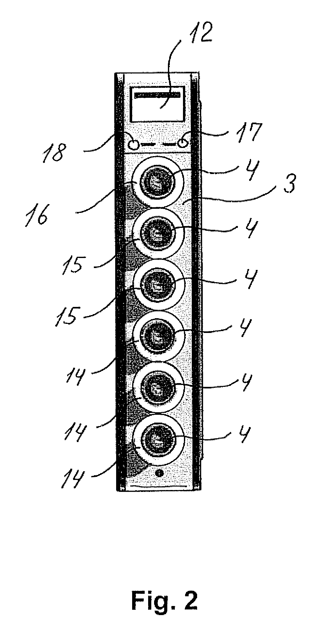
The present invention relates to units or modules for data acquisition that may either be used as stand alone units or be used to form a modular system where a plurality of modules are mounted together in a frame or rack structure as well as combinations of such stand-alone units and frames. More specifically the invention relates to a module for data acquisition comprising a detachable front unit (3) for releasable attachment to said module (1) comprising one or more first electrical connector means (4) for receiving data or signals from external units, such as microphones and / or accelerometers, and / or for providing data or signals, such as control signals, to external units; a main body comprising means (6) of establishing electrical connection to said one or more connector means (4) in said front unit (3), when said front unit (3) is connected to said module (1); and where the main body being furthermore provided with data output connector means (10); whereby data or signals provided to the module (1) via said one or more first electrical connector means (4), or processed versions of such signals or data, can be provided from said module (1) to one or more external units, such as a PC, via said data output connector means (10).

Description

TECHNICAL FIELD[0001]The present invention relates generally to units or modules for data acquisition that may either be used as stand-alone units or be used to form a modular system where a plurality of modules are mounted together in a frame or rack structure. The present invention relates more specifically to input and / or output means for providing communication with external units, such as transducers, various kinds of signal processing equipment or analysers and / or computers and to output means facilitating communication with external receptor equipment, such as a PC, via a standard LAN connection.BACKGROUND OF THE INVENTION[0002]Data acquisition equipment is generally well known within the art for instance for collecting, registering and processing signals from microphones or accelerometers used to monitor the acoustical environment in for instance airports or inside the cabin of an airplane, train or automobile or for connecting a number of transducers, such as microphones or...

Claims


Application Information

Patent Timeline
IPC IPC(8): H05K5/00
CPCH05K7/1461
Inventor NIELSEN, CARLKROMAN, LARSVASTRUP, AAGELARSEN, HALGEHANSEN, CARSTENTHESTRUP, LARS
Owner BRUEL & KJAER SOUND & VIBRATION MEASUREMENT
Learn More