
Actuator with self-locking helical gears for a continuously variable valve lift system

Inactive Publication Date: 2009-11-19
TAYE ELIAS
View PDF9 Cites 6 Cited by
  • Summary
  • Abstract
  • Description
  • Claims
  • Application Information

AI Technical Summary

Benefits of technology

[0009]Briefly described, a CVVL system in accordance with the present invention includes a self-locking helical gear pair with, optionally, an additional gear system to increase output torque of the actuator. The self-locking helical gear pair provides higher forward efficiency, being at least twice that of a conventional worm gear actuator, and a fully mechanically self-locking feature. The actuator therefore requires a smaller motor to perform the same actuation as a prior art worm-gear system, which reduces the cost and volume of the CVVL system. Thus, a CVVL system in accordance with the present invention is significantly less bulky and costly than a comparable prior art system and is fully mechanically self-locking over the entire range of action.
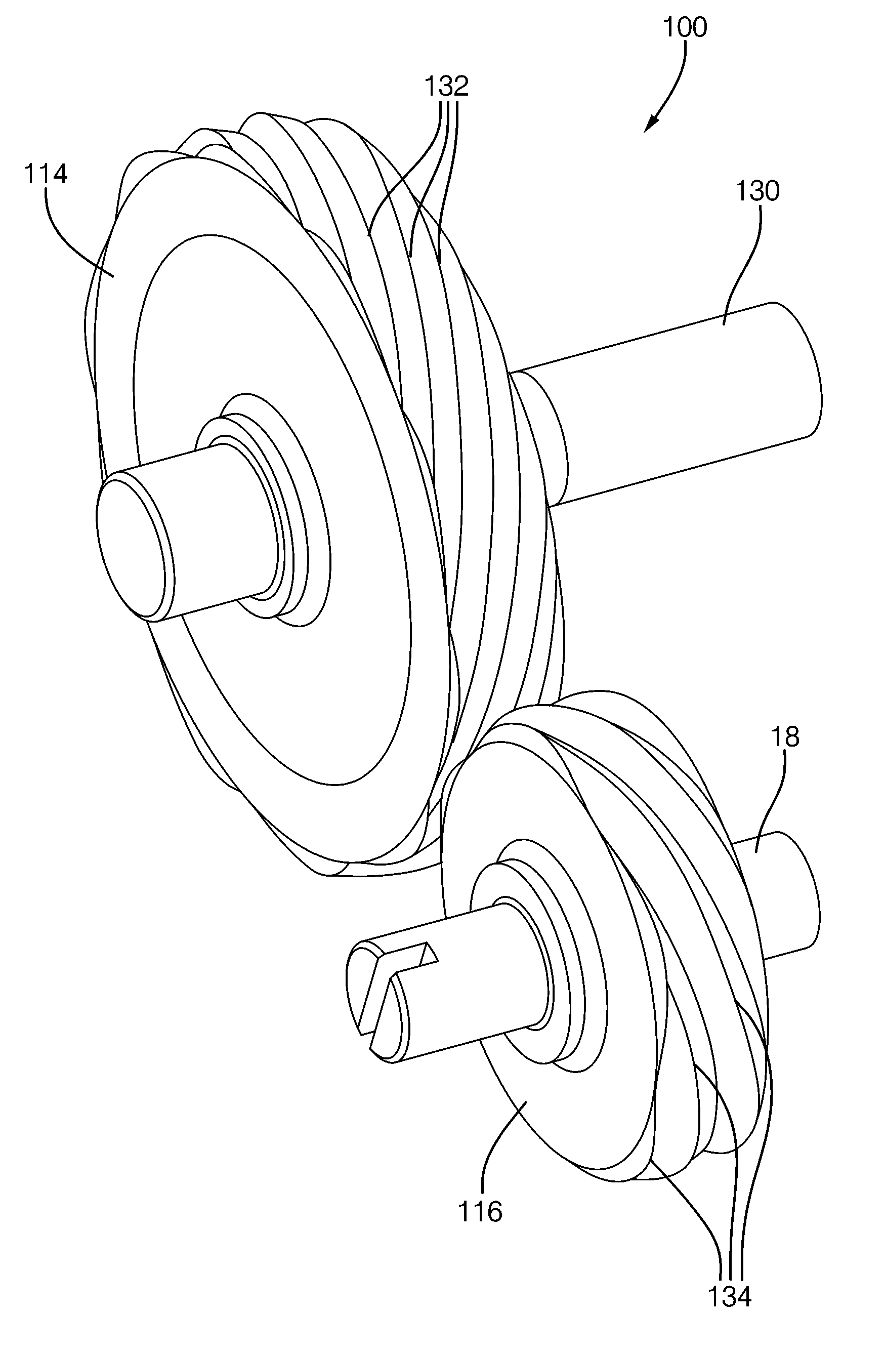
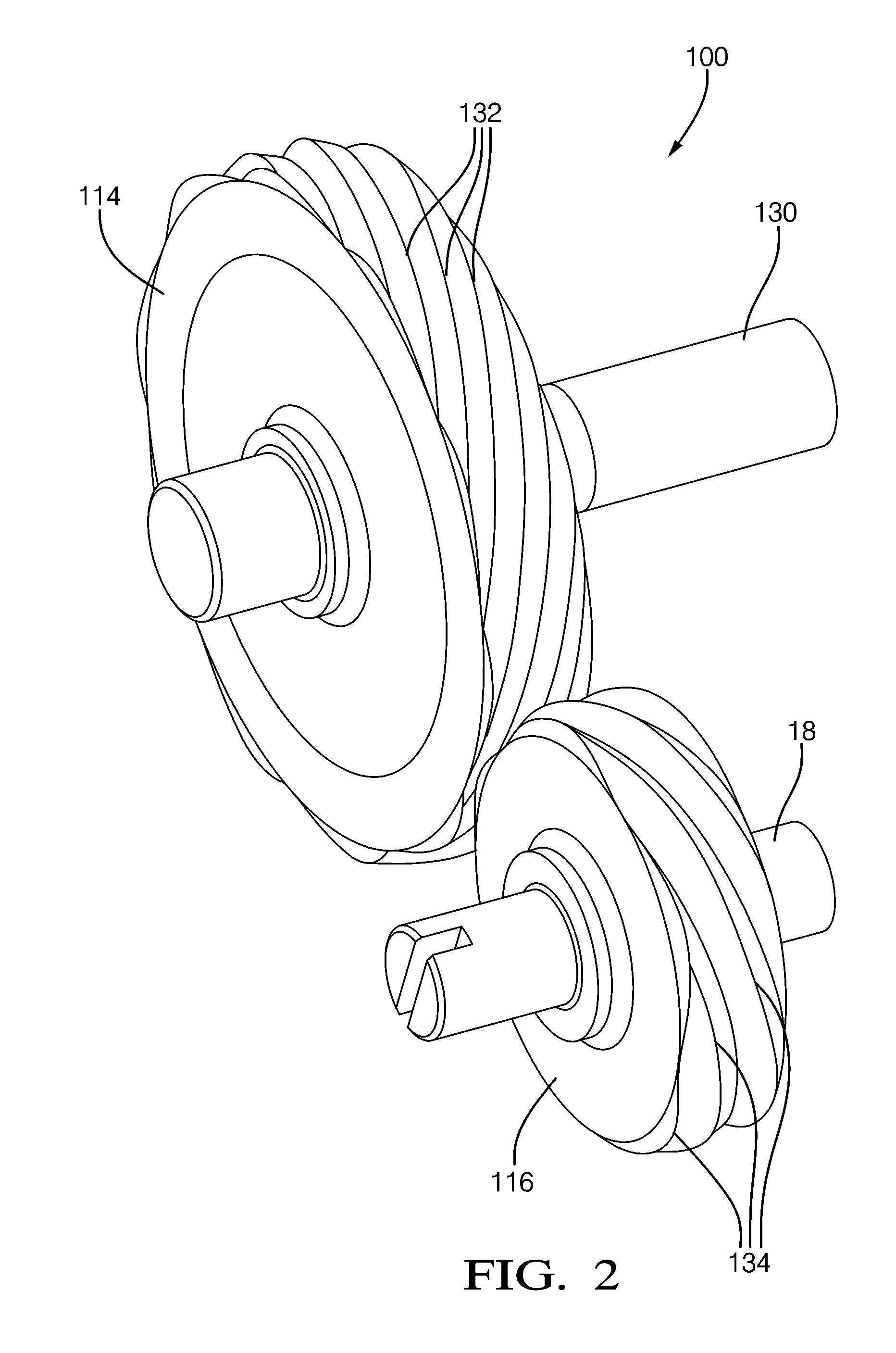
[0010]The CVVL system includes a self-locking gear pair comprising two helical gears that have a high radial pressure angle, between about 45° and about 75°, and a high helix angle, between about 60° and about 80°. These gears require high addendum modification (positive and negative profile shift) such that the pitchpoint is beyond the active portion of the contact line, which creates a mechanically self-locking condition against backdrive. Tooth profiles may be symmetric, although an asymmetric profile is presently preferred to reduce contact stress and permit higher torque density. Preferably, the helical gears are discontinuous and comprise a plurality of spur gear slices which can produce smoother power transmission and lower transverse contact ratio. Such discontinuous helical gears are significantly less costly to manufacture.

Problems solved by technology

An inherent drawback of worm gear actuators is very low mechanical efficiency; that is, because of the high sliding velocity due to a small worm lead angle, a high percentage of the actuator torque, typically more than 50%, is consumed in friction with the pinion gear.
Because of the low mechanical efficiency, the actuator requires a relatively large and expensive motor to drive the worm gear.

Method used


Image

  • Actuator with self-locking helical gears for a continuously variable valve lift system
  • Actuator with self-locking helical gears for a continuously variable valve lift system
  • Actuator with self-locking helical gears for a continuously variable valve lift system

Examples


Embodiment Construction

[0022]Self-locking helical gears are known in the prior art from relatively few publications that demonstrate the possibility of designing a helical gear pair to be self-locking and provide general guidelines on how to obtain the self-locking feature. Despite these early publications, however, self-locking helical gears have not been widely reduced to practice, especially in automotive applications, such as the present invention. Further, the CVVL system disclosed herein includes improvements that are novel in the art, including: laminated helical gears to reduce fabrication costs; a preferred range of pressure angle and helical angles appropriate for steel gears.

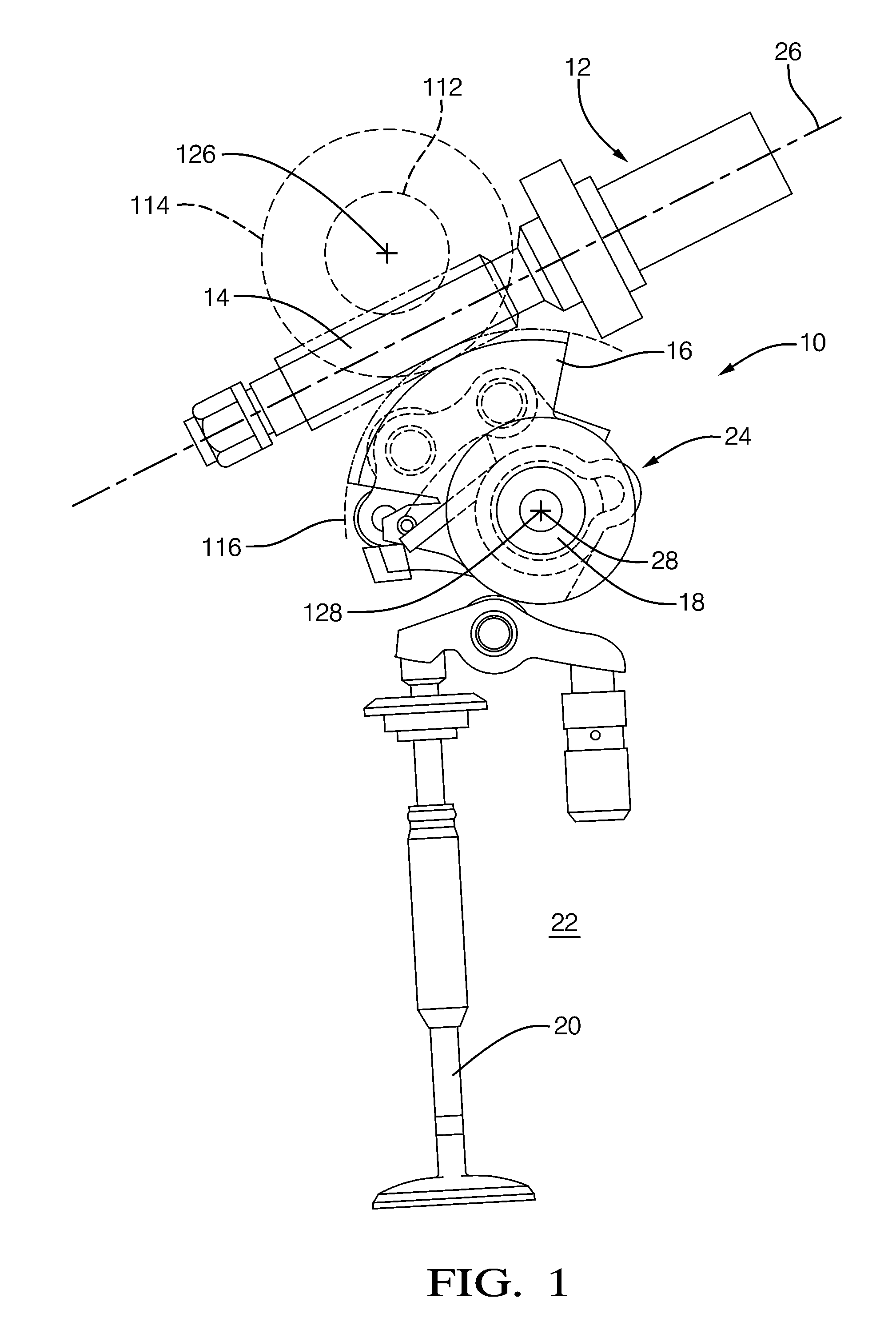
[0023]Referring to FIG. 1, in a prior art CVVL system 10, substantially as disclosed in U.S. Pat. No. 7,174,887 to Shuichi Ezaki, which is herein incorporated by reference, a motor actuator 12 causes rotation of a worm 14, causing a worm gear segment 16, also known as a worm wheel, to rotate a control shaft 18 on which the ...


PUM


Abstract

A CVVL system including a self-locking helical gear pair with, optionally, a transmission to increase output torque of the actuator. The self-locking helical gear pair provides high forward efficiency and a fully mechanically self-locking feature. The actuator therefore requires a smaller motor to perform the same actuation as a prior art worm-gear system. The CVVL system comprises two helical gears having a radial pressure angle {acute over (α)} between 45° and 75° and a helix angle β between 60° and 80°. An asymmetric tooth profile is presently preferred, reducing contact stress and permitting higher torque density. Preferably, the helical gears are discontinuous and comprise laminated spur gear slices and hence are less costly to produce than continuous helical gears. Configurations are possible within the scope of the present invention include a single stage gear system; a multiple stage gear system; a planetary gear system; and an internal or external gear system.

Description

TECHNICAL FIELD[0001]The present invention relates to variable valve lift systems for combustion valvetrains of internal combustion engines; more particularly, to such systems wherein the valve may be lifted to any height in a continuous range of heights, defined herein as “continuously variable valve lift” (CVVL); and most particularly, to such a system having a high-efficiency actuator employing a self-locking helical gear arrangement.BACKGROUND OF THE INVENTION[0002]It is well known in the internal combustion engine arts to provide an engine with means for varying the lift of one or more combustion valves to improve engine efficiency and / or decrease emissions under certain engine operating conditions. Some known systems vary valve lift between two steps, for example, fully open (activated) and non-opening (deactivated); such systems can be thought of as switchable systems. Other systems, especially in the compression-ignited engine arts, benefit from mechanisms which are capable ...

Claims


Application Information

Patent Timeline
IPC IPC(8): F01L1/34F16H1/04F16H1/08
CPCF01L13/0021Y10T74/19679Y10T74/19698F16H1/08
Inventor TAYE, ELIAS
Owner TAYE ELIAS
Learn More