
Driver assistance system having a device for recognizing stationary objects

Inactive Publication Date: 2009-11-12
ROBERT BOSCH GMBH
View PDF11 Cites 21 Cited by
  • Summary
  • Abstract
  • Description
  • Claims
  • Application Information

AI Technical Summary

Benefits of technology

[0012]The exemplary embodiments and / or the exemplary methods of the present invention having the features described herein offers the advantage that it makes possible, with regard to differentiation between stationary and moving objects, a system behavior that is more situationally appropriate and / or more comprehensible to the driver.
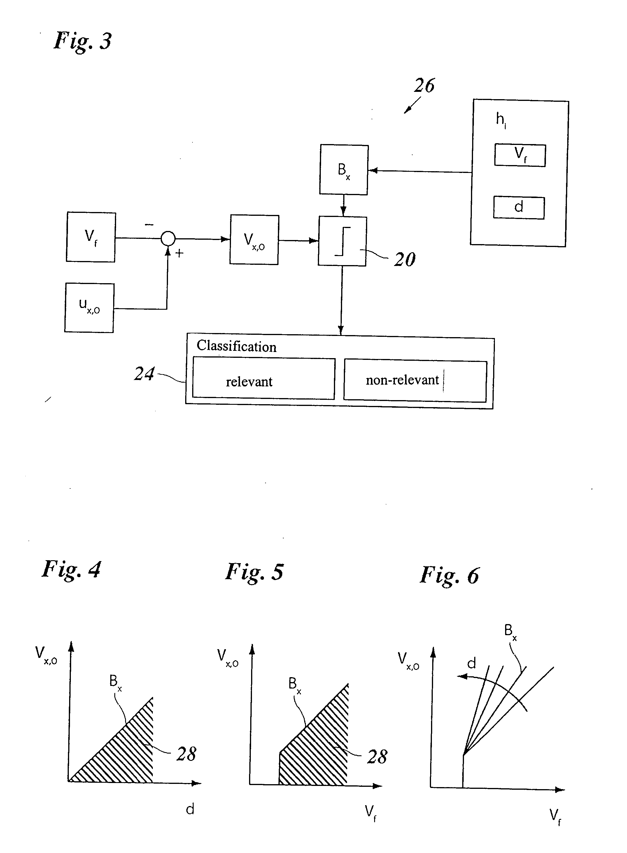
[0014]It is thus possible, in situations in which the data furnished by the localizing system regarding the own-vehicle motion and relative motion are highly reliable, to lower the threshold value so that a sharper distinction can be made between stationary and moving objects; whereas on the other hand, as the uncertainty of the data rises, the threshold value is increased in order to prevent misclassifications. The limited perceptual capability of the driver can likewise be better taken into account by varying the threshold value.

Problems solved by technology

The ACC systems that are already in practical use today are generally designed for use on expressways or well-constructed main roads, and therefore react in principle only to moving objects, e.g. to preceding vehicles, while stationary objects are ignored, proceeding from the assumption that on expressways such objects are normally not located on the roadway, and because it is technically very difficult to perform a relevance classification of stationary objects on the basis of radar data.
In practice, however, a difference of exactly zero is never obtained even for stationary objects, because of unavoidable measurement inaccuracies.
With greater demands in terms of the accuracy of object classification, however, it becomes difficult to select a suitable threshold value.
If the threshold value is too low, inaccuracies in the velocity measurements made with the aid of the localizing system—and, for the own vehicle, with the aid of a rotation-speed measuring device and a yaw rate sensor in the case of transverse motions—can result in misclassifications.
This is particularly problematic when a classification as to movable and non-movable objects is also necessary, since once an object has been incorrectly classified as moving, from that time onward it is always considered movable.
In such cases, in particular, the own-vehicle velocity measurement is distorted by filter transit times and other filter effects such as signal delays, under- and overshoots, and the like.
Inaccuracies in measurements made with the localizing system are a further source of errors.
Additional error sources result from the fact that in most cases different filters or filter algorithms are used for processing the data from various sensor systems, so that, for example, different signal delays simulate differences that do not actually exist.
This problem becomes worse when, for more-accurate sensing of the traffic environment, a plurality of sensor systems are used whose measurement results are then fused with one another.
These shortcomings prove particularly disruptive in city traffic or in general for low-speed driving, i.e. in situations in which the refined driver assistance systems are intended to be used.
A further complicating factor is that the own-vehicle velocity measurement becomes very inaccurate specifically at very low speeds.
At a low rotation speed, the pulse frequency of these pulse generators is so low that an accurate velocity measurement is no longer possible.
Specifically, if the driver assistance system, because of the high sensitivity of its sensor suite, behaves differently than the driver would expect based on his or her limited perception capabilities, the system's behavior is implausible from the driver's point of view; this is often felt to be irritating, and interferes with acceptance of the driver assistance system.

Method used


Image

  • Driver assistance system having a device for recognizing stationary objects
  • Driver assistance system having a device for recognizing stationary objects
  • Driver assistance system having a device for recognizing stationary objects

Examples


Embodiment Construction

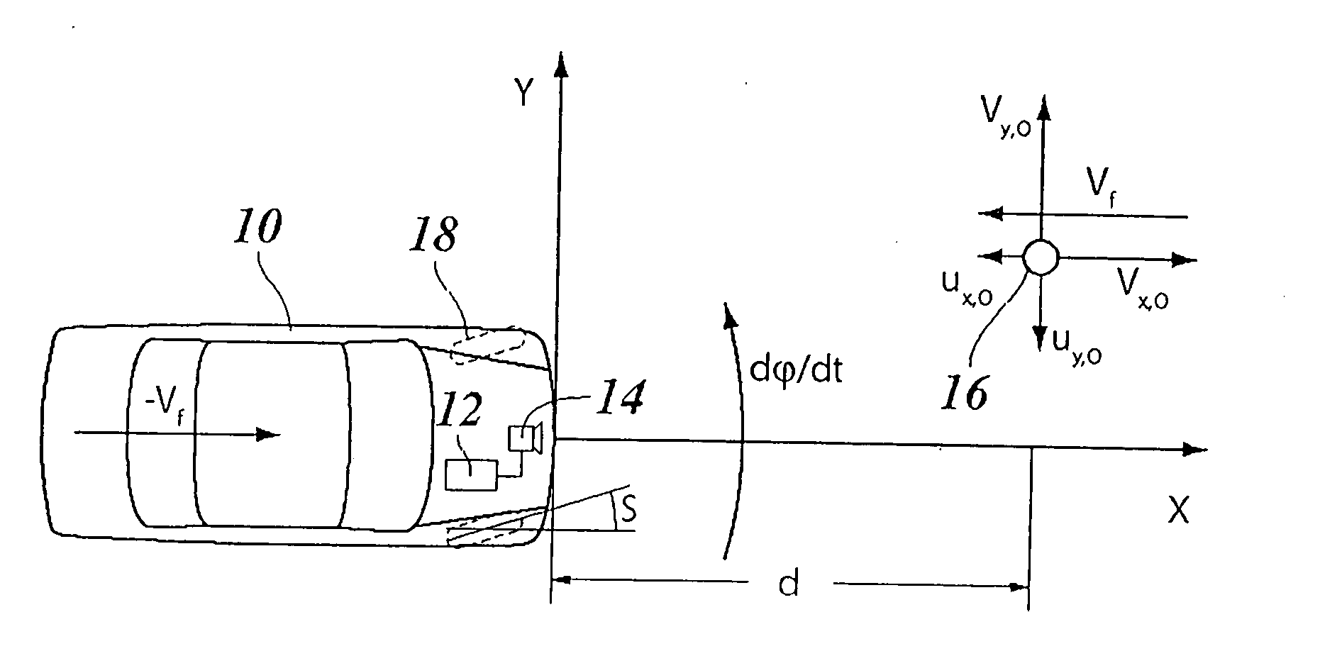
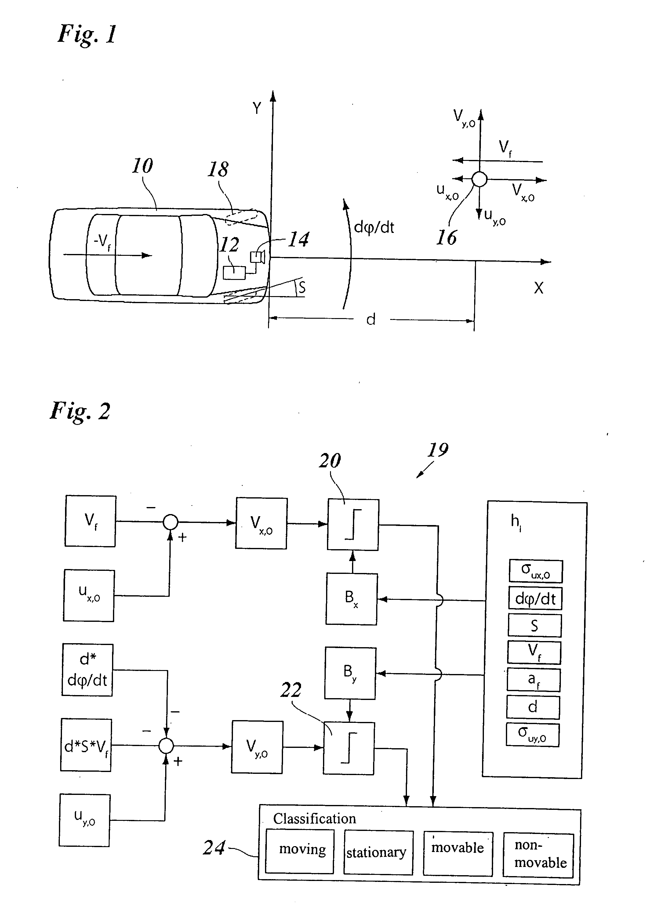
[0028]FIG. 1 depicts a vehicle 10 that is equipped with a driver assistance system 12, for example an ACC system. A radar sensor 14 is built in as a localization system. In the example shown, a single object 16, whose distance d in direction X (travel direction of vehicle 10) and relative velocity ux,O in the X direction can be measured directly, is located in the localization region of the radar sensor. Radar sensor 12 has a certain angular resolution capability and can therefore also measure the azimuth angle at which object 16 is being viewed with respect to the X axis. From this, the transverse position of the object in the direction of the Y axis can be calculated with the aid of the measured distance d, and the relative velocity uy,O in the Y direction can be calculated by time derivation.

[0029]Appearing below object 16 in FIG. 1 is a vector Vf that indicates the “inherent velocity” of vehicle 10. More precisely, this vector indicates the apparent relative velocity that would ...


PUM


Abstract

A driver assistance system for motor vehicles, having a localization system for localizing objects in the surroundings of the vehicle and having a device for recognizing stationary objects by comparing the difference between the relative motion of the object and the inherent motion of the vehicle with a threshold value, wherein the device is embodied to vary the threshold value as a function of variables that influence the accuracy with which the relative and inherent motions are determined.

Description

RELATED APPLICATION INFORMATION[0001]The present application claims the benefit of International Patent application no. PCT / EP2006 / 060810, which was filed on Mar. 16, 2006, and which claims priority to and the benefit of German patent application no. DE 102005017422.1, which was filed in Germany on Apr. 15, 2005, the disclosures of which are both hereby incorporated by reference.FIELD OF THE INVENTION[0002]The present invention relates to a driver assistance system for motor vehicles, having a localizing system for localizing objects in the vehicle's surroundings, and having a device for comparing the difference between the relative motion of the object and the inherent motion of the vehicle with a threshold value.BACKGROUND INFORMATION[0003]Driver assistance systems serve to assist the driver when operating a motor vehicle, to warn him or her of impending hazards, and / or to automatically initiate actions to mitigate the consequences of an imminent collision. The driver assistance s...

Claims


Application Information

Patent Timeline
IPC IPC(8): B60Q1/00G01S13/931
CPCB60W40/02B60W40/11B60W40/112B60W40/114B60W50/14G01S2013/9325G01S13/931G08G1/16G01S2013/9353G01S2013/9321G01S7/415G08G1/166G01S2013/932
Inventor WEILKES, MICHAELBOECKER, JUERGENPETSCHNIGG, PETER
Owner ROBERT BOSCH GMBH
Learn More