
Cover deploying system utilizing active material actuation

a technology of active material and deployment system, which is applied in the direction of windows, vehicle components, transportation and packaging, etc., can solve the problems of increased weight, volume, cost, noise, and the inability to deploy the cover, so as to reduce the weight of the equivalent component, reduce the cost, and prolong the battery life of the vehicle

Inactive Publication Date: 2009-11-12
GM GLOBAL TECH OPERATIONS LLC
View PDF6 Cites 12 Cited by
  • Summary
  • Abstract
  • Description
  • Claims
  • Application Information

AI Technical Summary

Benefits of technology

The present invention provides a system for deploying and stowing a cover, such as a sunshade for a vehicle, using active material activation. The system is useful for providing energy conservation, reducing costs, and offers more robust design capabilities, packaging flexibility, and accommodation than conventional actuators. The system includes a mechanical assembly and an active-material actuator, which is drivenly coupled to the assembly and configured to impart a torque or linear translation force upon at least one of the parts so as to cause the part to rotatably or linearly translate as a result of the change. The assembly is caused to reconfigure between the deployed and stowed conditions as a result of the translation, and the cover is deployed or stowed as a result of the reconfiguration. The invention addresses the concerns of manually and electro-mechanically / magnetically / hydraulically deployed prior art systems.

Problems solved by technology

However, various concerns relating to conventional covers remain in the art.
Where an occupant is not present, the cover cannot be deployed.
As a result, excessive temperature rise (and direct exposure of interior surfaces to solar radiation) in parked vehicles due to solar energy passing through glazing often occur rapidly, resulting at least in an unpleasant situation upon vehicle entry and more rapid degradation of UV sensitive interior materials.
The electro-mechanical motors involved therewith, however, present there own concerns related to increased weight, volume, cost, noise, and likelihood of failure.
Moreover, these types of mechanisms further present concerns related to up-keep, repair and replacement, as well as the establishment of an additional battery load.
Concerns remain here as well, as the manual deployment and stowing of these larger shades take even more time, are inconvenient, and when not in use require significant storage space.

Method used


Image

  • Cover deploying system utilizing active material actuation
  • Cover deploying system utilizing active material actuation
  • Cover deploying system utilizing active material actuation

Examples


Embodiment Construction

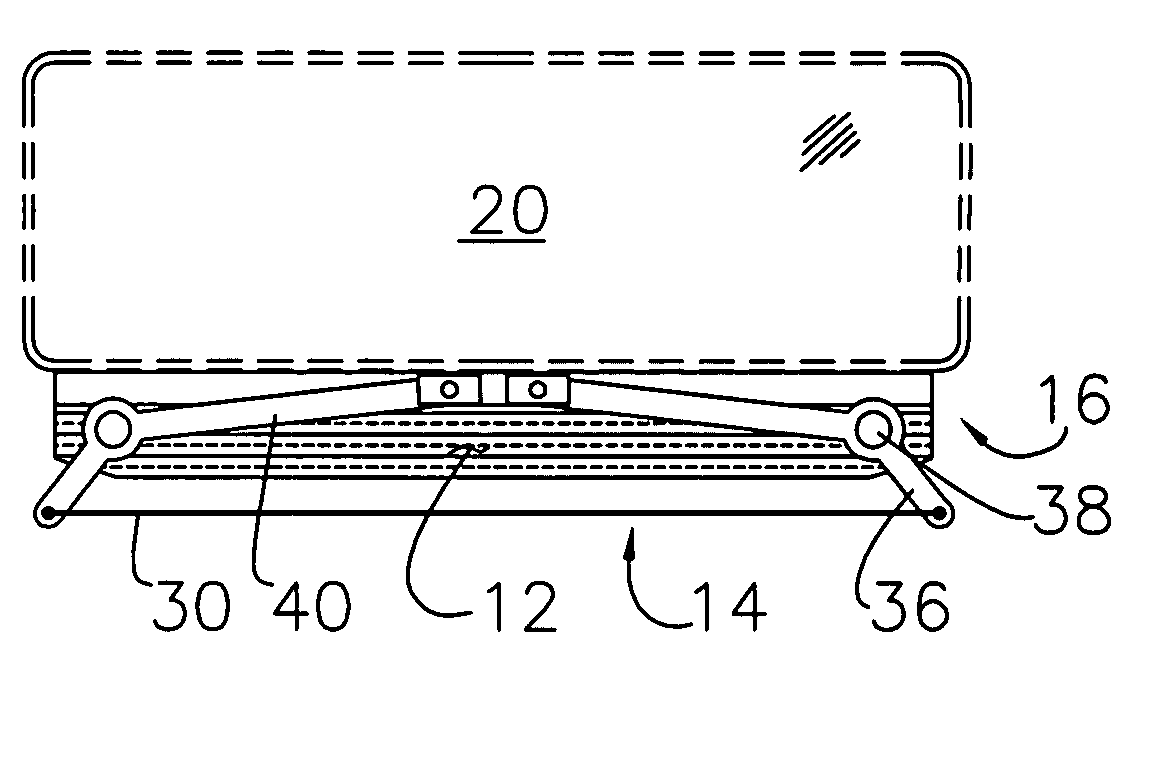
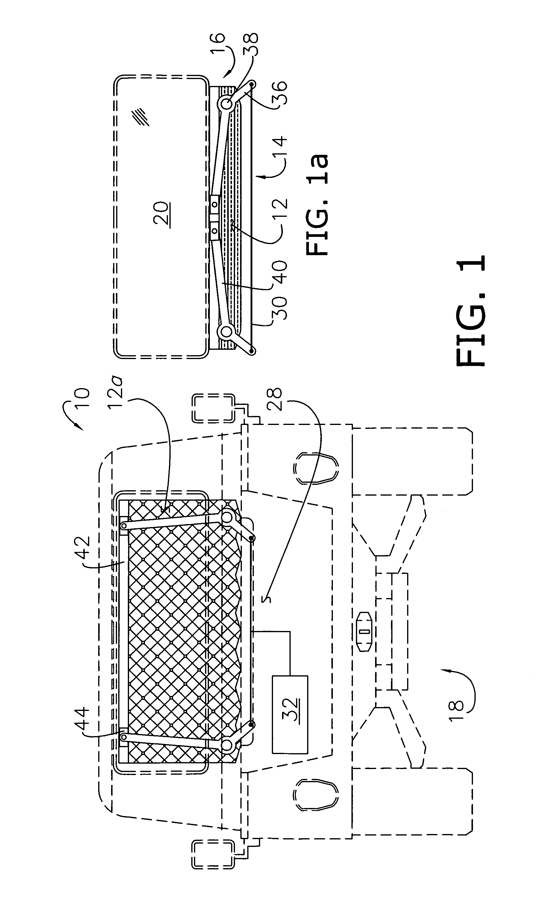
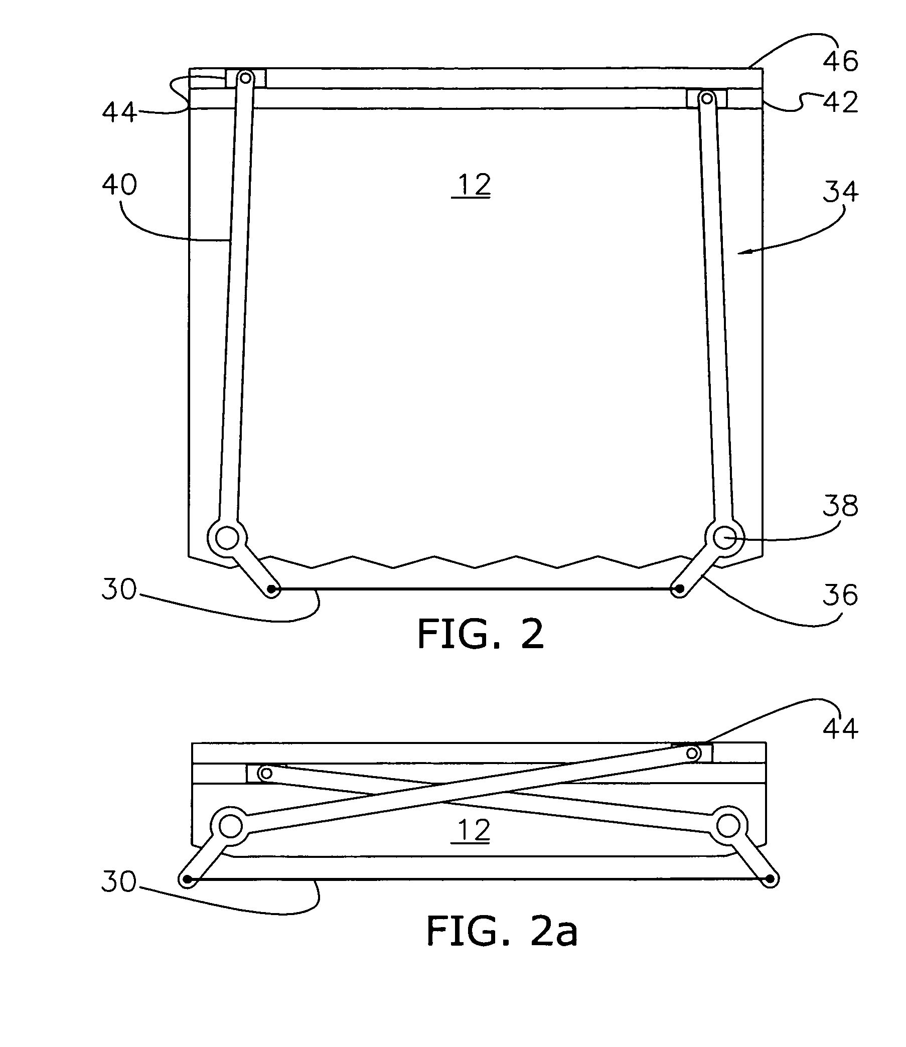
[0041]Turning first to FIGS. 1 and 1a, the present invention concerns a system 10 adapted for deploying and stowing a cover 12, and including an active-material based actuator 14 and a reconfigurable mechanical assembly 16 driven by the actuator 14. Although described herein with respect to a vehicle 18, such as an automobile, it is appreciated that the benefits of the present invention can be utilized in other settings wherein utilizing active material to deploy a cover more efficiently and reliably is desired. For example, the inventive system 10 may be utilized in conjunction with residential or commercial buildings; or to selectively deploy a cargo net or safety beam, so as to protect a three-dimensional space or catch loose objects. As such, the term “cover” is not limited to the embodiments illustrated herein, and shall include, for example, sunscreens, sun sheets, sunshades, interfering window slats (also know as “blinds”), cargo bed covers, storage well / bin covers, partition...


PUM


Abstract

A system for deploying and stowing a cover, including a mechanical assembly coupled to the cover, preferably comprising a plurality of deploy arms and synchronization means, and reconfigurable between deployed and stowed conditions, and further including an actuator presenting an active material element operable to undergo a change, when activated, and operable to cause the assembly to reconfigure as a result of the change.

Description

CROSS REFERENCE TO RELATED APPLICATIONS[0001]Reference is made to commonly assigned U.S. patent application Ser. No. 12 / 059,861, filed on Mar. 31, 2008, and entitled METHODS OF DEPLOYING A COVER UTILIZING ACTIVE MATERIAL AND AN EXTERNAL HEAT SOURCE; and U.S. patent application Ser. No. 11 / 856,744, filed on Sep. 18, 2007, and entitled ACTIVE MATERIAL ACTIVATED COVER, the disclosures of which are incorporated herein by reference.BACKGROUND[0002]1. Field of the Invention[0003]The present disclosure relates to systems for deploying covers, sunshades, screens, partitions, blinds, safety cargo beams / nets and the like (collectively referred to herein as “covers”), and more particularly, to a deployment system utilizing active material actuation and a reconfigurable mechanical assembly.[0004]2. Discussion of Prior Art[0005]A variety of covers have long been developed to serve as barriers to heat energy and / or to direct exposure to variously the IR, UV, and visible portions of the solar spec...

Claims


Application Information

Patent Timeline
Patent Type & Authority Applications(United States)
IPC IPC(8): B60J3/02
CPCB60J1/2011B60J1/2055B60J1/2019
Inventor GAO, XIUJIEMANKAME, NILESH D.BROWNE, ALAN L.JOHNSON, NANCY L.
Owner GM GLOBAL TECH OPERATIONS LLC
Learn More