
Detachable electric headrest

a headrest and electric technology, applied in the field of electric headrests, can solve the problems of complicated structure of headrests and difficulty in detaching headrests from seat frames

Inactive Publication Date: 2009-11-05
HYUNDAI MOTOR CO LTD +1
View PDF8 Cites 8 Cited by
  • Summary
  • Abstract
  • Description
  • Claims
  • Application Information

AI Technical Summary

Benefits of technology

The present invention provides an electric headrest that can be easily attached and detached from a seat frame. The detachable electric headrest includes a headrest pole, an ascending and descending slider, an elastic member, and a locking bar. The elastic member is selectively inserted into the engaging depression of the headrest pole and the locking bar is pressed by the seat frame to lower the cut depression when the ascending and descending slider reaches its upper most position. The elastic member can be moved to cut depression of the locking bar and disengaged from the headrest pole when the headrest pole is detached from the detachment depression of the ascending and descending slider. The detachable electric headrest provides a convenient and easy way to adjust the headrest position.

Problems solved by technology

However, in the above-described electric headrest, there is a problem in that it is difficult to detach a headrest from a seat frame due to the electrical connection structure between the seat frame and the headrest.
Furthermore, in the case where a folding function is applied to the electric headrest, there are problems in that the structure thereof becomes complicated, and in that there are technical difficulties in applying the folding function to the electric headrest.

Method used


Image

  • Detachable electric headrest
  • Detachable electric headrest
  • Detachable electric headrest

Examples


Embodiment Construction

[0028]Reference will now be made in detail to various embodiments of the present invention(s), examples of which are illustrated in the accompanying drawings and described below. While the invention(s) will be described in conjunction with exemplary embodiments, it will be understood that present description is not intended to limit the invention(s) to those exemplary embodiments. On the contrary, the invention(s) is / are intended to cover not only the exemplary embodiments, but also various alternatives, modifications, equivalents and other embodiments, which may be included within the spirit and scope of the invention as defined by the appended claims.

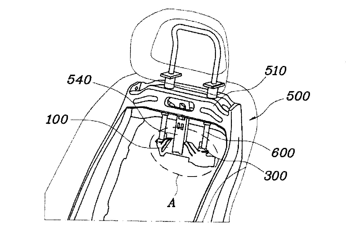
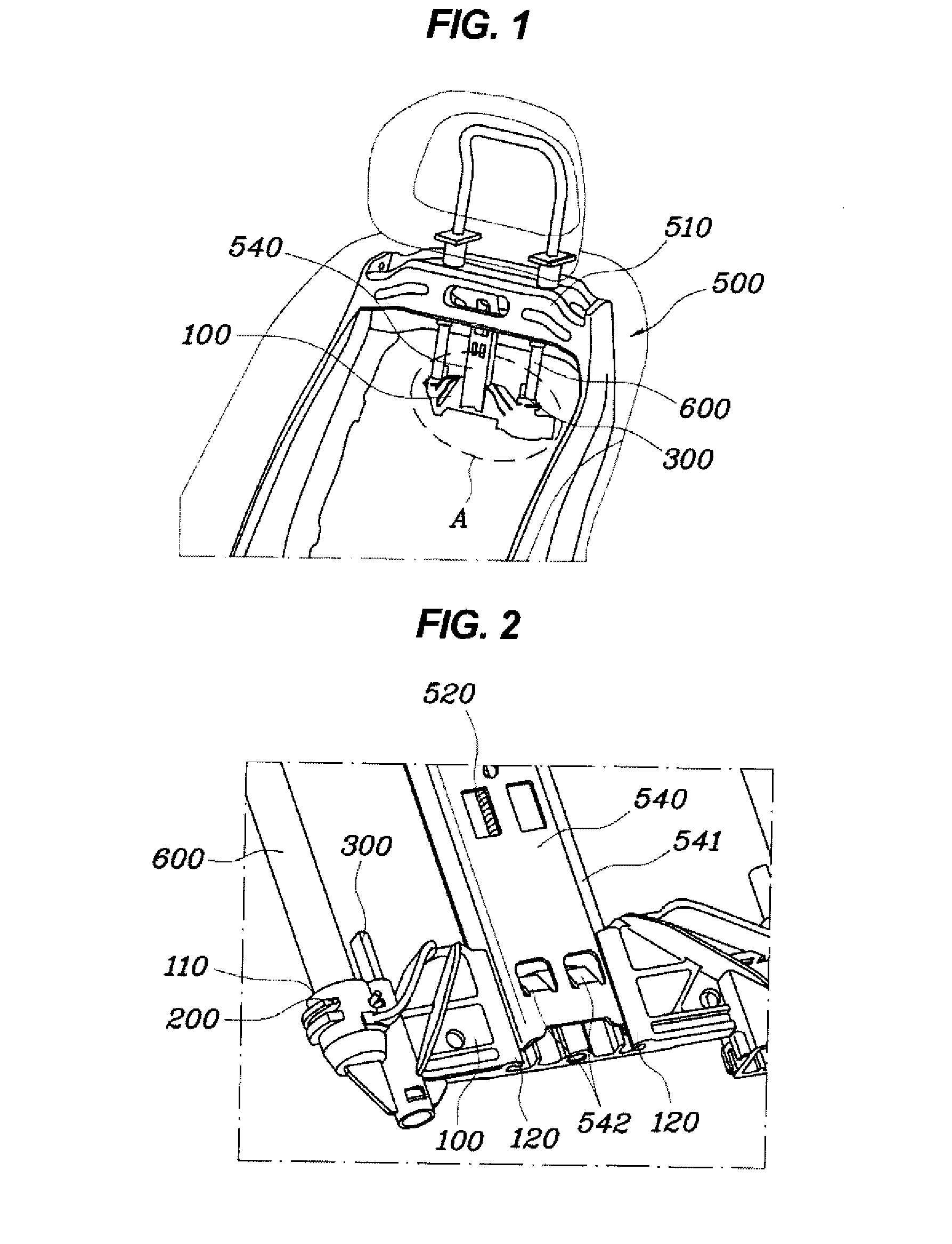
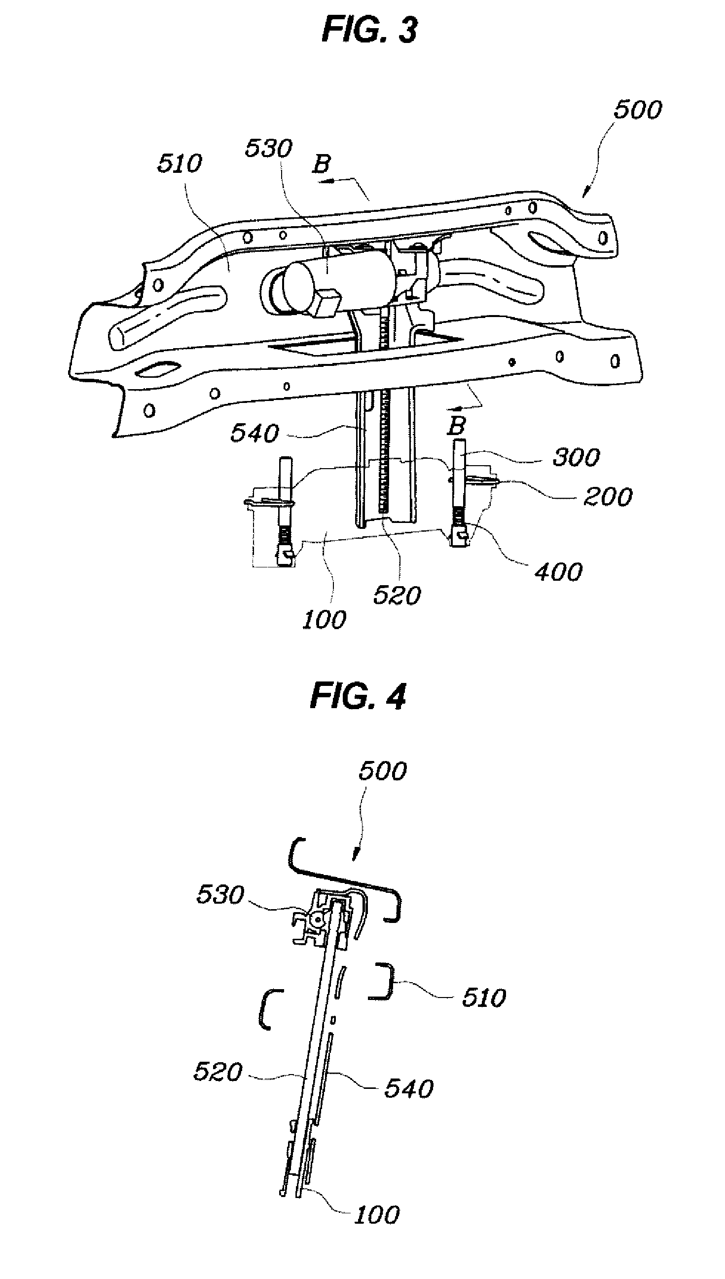
[0029]As shown in FIGS. 1 to 5, an electric headrest according to the present invention is implemented to have a structure in which a headrest pole 600 is attachably detached from a seat frame 500 when an ascending and descending slider 100 is moved its uppermost position.

[0030]In greater detail, the ascending and descending slider 10...


PUM


Abstract

The detachable electric headrest includes a headrest pole, an ascending and descending slider, elastic pins, and locking bars. The headrest pole is configured such that engaging depressions are formed in the lower end portion thereof. The ascending and descending slider is provided with detachment depressions, into which the respective lower end portions of the headrest pole are inserted, and is mounted to the fastening bracket of a seat frame so as to be raised and lowered. The elastic pins are mounted in the respective detachment depressions so as to be inserted into the engaging depressions of the inserted headrest pole. The locking bars are configured such that cut depressions, in which the elastic pins can be moved, are formed in respective upper ends thereof, and are configured to be elastically supported to the ascending and descending slider.

Description

CROSS-REFERENCE TO RELATED APPLICATION[0001]The present application claims priority to Korean Application No. 10-2008-0040558 filed Apr. 30, 2008, the entire contents of which application is incorporated herein for all purposes by this reference.BACKGROUND OF THE INVENTION[0002]1. Field of the Invention[0003]The present invention relates generally to an electric headrest, which can be easily attachably detached from a seat frame.[0004]2. Description of Related Art[0005]A typical vehicle headrest is mounted to the upper end of the back of a seat to support the head and neck area of a passenger. This headrest not only can prevent the head and neck portions from being damaged as the neck is moved backwards when a rear-end collision occurs, but also can provide comfort by coming into close contact with the head portion during normal driving.[0006]The above-described headrest includes a pad, which is made of cushion material, and a headrest pole, which is connected to a seat frame. The h...

Claims


Application Information

Patent Timeline
Patent Type & Authority Applications(United States)
IPC IPC(8): A47C7/38
CPCB60N2/4829B60N2/829
Inventor KIM, SANG HOMA, CHAE HOONSEO, JIN HO
Owner HYUNDAI MOTOR CO LTD
Learn More