
Method and apparatus for identifying noise sources

a technology of noise source and method, applied in the field of apparatus for acquiring data, can solve the problems of affecting the noise quality of the noise source, the noise of high-speed exhaust flow, and the different surfaces of the duct and inlet of the jet engine, etc., and the current use of methods for obtaining noise using arrays of microphones is limited to the array size or the location

Active Publication Date: 2009-10-29
THE BOEING CO
View PDF4 Cites 24 Cited by
  • Summary
  • Abstract
  • Description
  • Claims
  • Application Information

AI Technical Summary

Benefits of technology

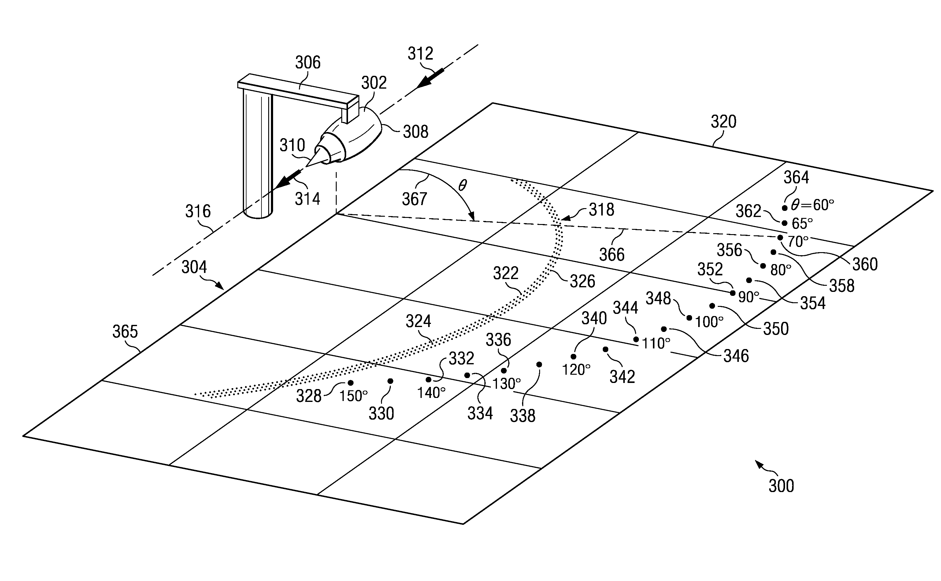
The patent describes a method and apparatus for identifying a breakdown of noise from a noise source. The method involves receiving noise data from an array of sound sensors on a ground plane, selecting a measurement point of interest, identifying a primary ray trace and a second bounding ray trace from a ray trace extending from a candidate sound source point to the measurement point of interest, identifying a first curve and a second curve from intersections of the surfaces created by rotating the first and second bounding ray traces with the ground plane, and selecting a set of sound sensors from the array of sound sensors using the first and second curves to identify a subarray. The method can help identify the source of noise and locate it accurately.

Problems solved by technology

For example, different surfaces within ducts and inlets of a jet engine may contribute noise during the operation of the jet engine.
For example, the high speed exhaust flow may contribute noise during the operation of the engine.
The currently used methods for obtaining noise using arrays of microphones are limited to the array size or location.
Further, the current methodologies may collect noise information with limited numbers of microphones.
This type of collection may result only in noise data being collected for a limited number of emission angles.

Method used


Image

  • Method and apparatus for identifying noise sources
  • Method and apparatus for identifying noise sources
  • Method and apparatus for identifying noise sources

Examples


Embodiment Construction

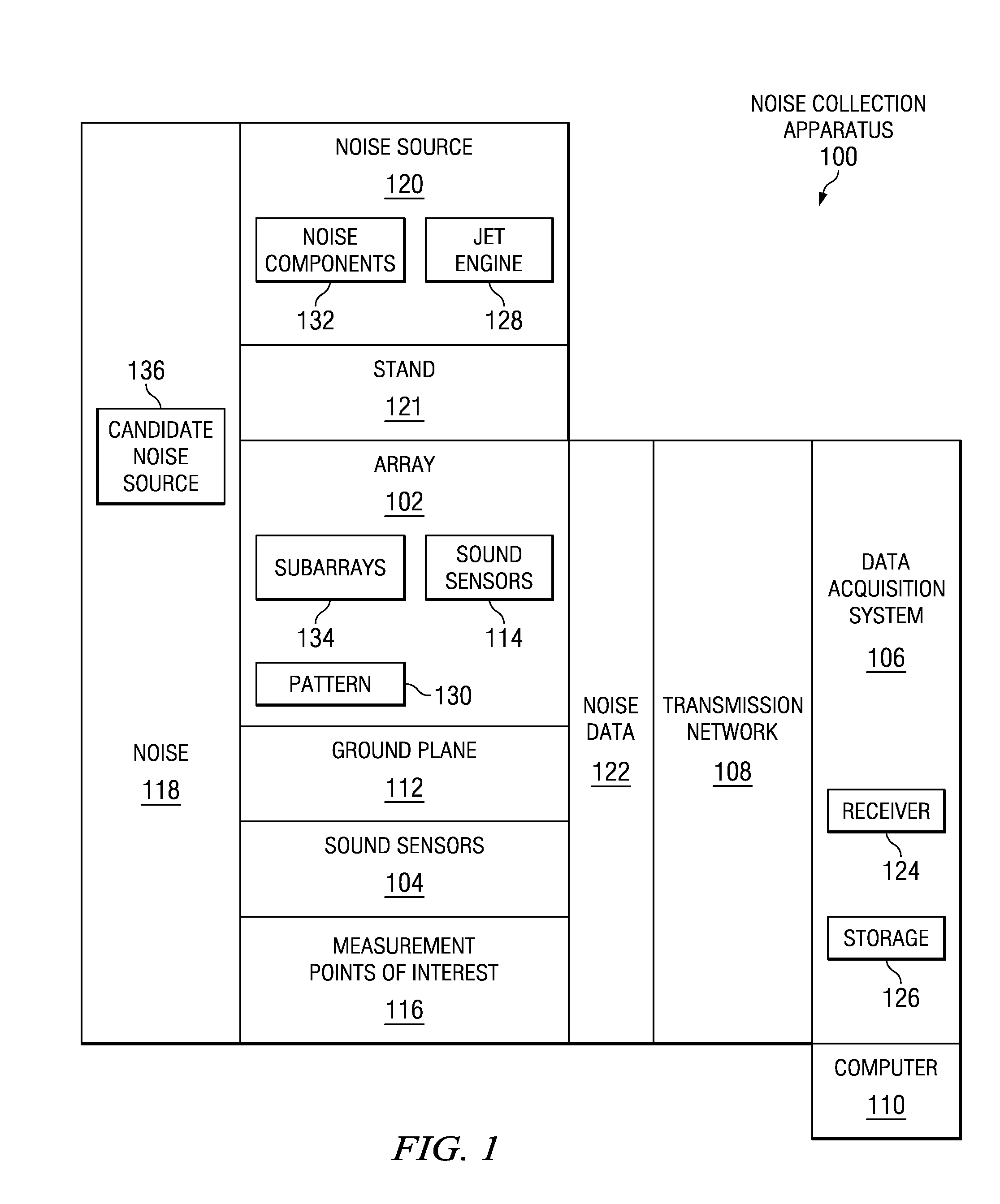
[0032]With reference now to the figures and in particular with reference to FIG. 1, a diagram illustrating a noise collection apparatus is depicted in accordance with an advantageous embodiment. In these examples, noise collection apparatus 100 comprises array 102, sound sensors 104, data acquisition system 106, transmission network 108, and computer 110.

[0033]In these examples, array 102 is located on ground plane 112. In these examples, ground plane 112 may be the ground on which array 102 is placed. In some cases, ground plane 112 may not be a plane in a mathematical sense, because the ground in which array 102 is placed may not be entirely flat. Array 102 is made up of sound sensors 114 in these examples. Additional sound sensors in sound sensors 104 may be located at measurement points of interest 116. These sound sensors may take various forms. For example, without limitation, sound sensors 104 and 114 may be microphones, hydrophones, laser sensors, seismometers, and other sui...


PUM


Abstract

A computer implemented method and apparatus for identifying component breakdown of noise sources. Noise data is received for a noise source from an array of sound sensors. Measurement points of interest, candidate sound source points along an axis, and array aperture angles are identified. Sets of first and second bounding traces are identified from ray traces extending from the candidate noise source points towards the measurement points of interest using the array aperture angles. The bounding ray traces are rotated around the axis to form sets of first and second surfaces. Sets of first and second curves are identified from an intersection of the sets of first and second surfaces with the ground plane. Sound sensors are selected from the array using the curves to form subarrays. The component breakdown of noise generated by the noise source is identified using noise data from sound sensors in the subarrays.

Description

BACKGROUND INFORMATION[0001]1. Field[0002]The present disclosure relates generally to an apparatus for acquiring data and a method for selecting subsets of the acquired data. Still more particularly, the present disclosure relates to an apparatus for acquiring data and a method for selecting data for use in identifying noise sources.[0003]2. Background[0004]The analysis of noise and the sources or causes of noise is often performed to understand the physics behind the noise generation. For example, an analysis may be performed to identify where the noise is coming from. This type of analysis may be performed in the testing of devices. For example, noise data may be collected for an aircraft engine, such as a jet engine. The noise data collected may be analyzed to determine what components within, and exterior to the jet engine contribute to the noise. These different components may also be referred to as a component noise sources.[0005]Different structures or components in a jet eng...

Claims


Application Information

Patent Timeline
Patent Type & Authority Applications(United States)
IPC IPC(8): H04B1/06
CPCG10L2021/02166G10L21/0272G01H3/00
Inventor UNDERBRINK, JAMES ROBERTBRUSNIAK, LEON
Owner THE BOEING CO
Learn More