
Overdriving apparatus and method thereof

Inactive Publication Date: 2009-10-29
NOVATEK MICROELECTRONICS CORP
View PDF2 Cites 7 Cited by
  • Summary
  • Abstract
  • Description
  • Claims
  • Application Information

AI Technical Summary

Benefits of technology

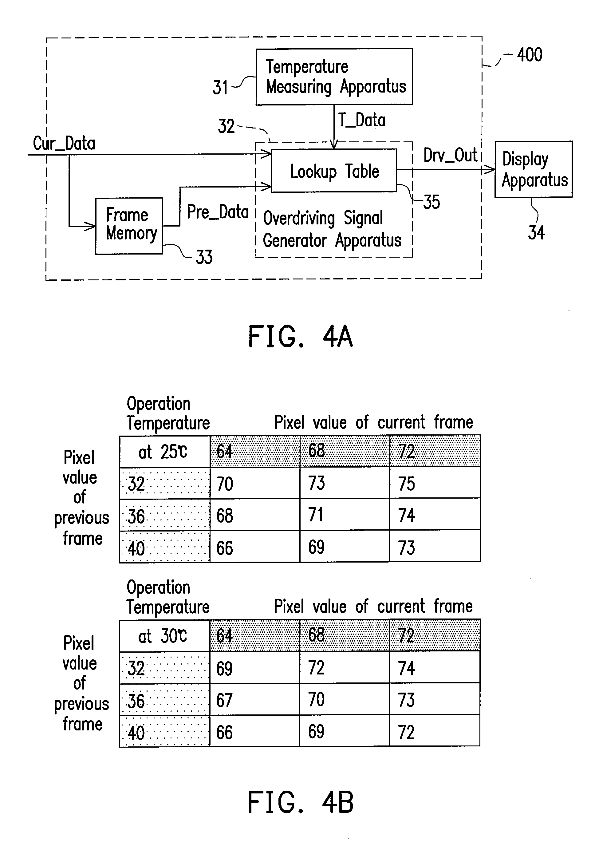
[0029]The overdriving apparatus and the overdriving method according to the present invention take the light transmittance varying according to temperature change into consideration (e.g., the viscosity and the refractive indices of liquid crystal molecules change by temperature variation so as to affect a response speed and the light transmittance of liquid crystal unit). It provides a temperature compensation to the generated overdriving signal. Therefore, the overdriving signal generator and the overdriving method in the present invention are adapted to provide better overdriving signals in wider temperatures range. The resulted over-driving signal won't be over-emphasized or under-emphasized. Compared to the conventional overdriving apparatus and the overdriving method thereof, an LCD employing the overdriving apparatus and the overdriving method according to the present invention can effectively eliminate the motion blur and double edge defects under temperature influence.

Problems solved by technology

However, when displaying dynamic images, the response speed of liquid crystal units of LCDs is generally too slow.
Therefore, there are often motion artifact or blurred images when an LCD displaying moving images, such artifacts will seriously deteriorate the displayed image quality.
In consequence, the conventional overdriving method is not suitable for a wide range of temperature, and an overdriving signal which is optimal for a particular temperature would be undershoot or overshoot for different temperature.
In a conventional overdriving method, the undershoot overdriving signal will result in too slow response speed and motion blur.
In contrast, the overshoot overdriving signal will result in too fast response speed and false double edge.
Therefore, the conventional overdriving signal generator may be affected by temperature variation, which leads to impacts on the display quality of the LCD apparatus.

Method used


Image

  • Overdriving apparatus and method thereof
  • Overdriving apparatus and method thereof
  • Overdriving apparatus and method thereof

Examples


Embodiment Construction

[0041]The present invention provides an overdriving apparatus and an overdriving method for a liquid crystal display (LCD) panel. The overdriving apparatus and the overdriving method are adapted for generating an overdriving signal in according to temperature variation, and therefore capable of providing a compensation corresponding to the temperature influence. Reference will now be made in detail to the present preferred embodiments of the invention, examples of which are illustrated in the accompanying drawings. Wherever possible, the same reference counting numbers are used in the drawings and the description to refer to the same or like parts.

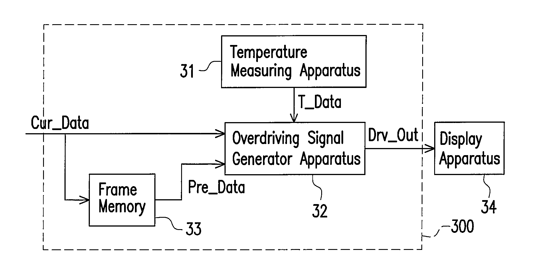
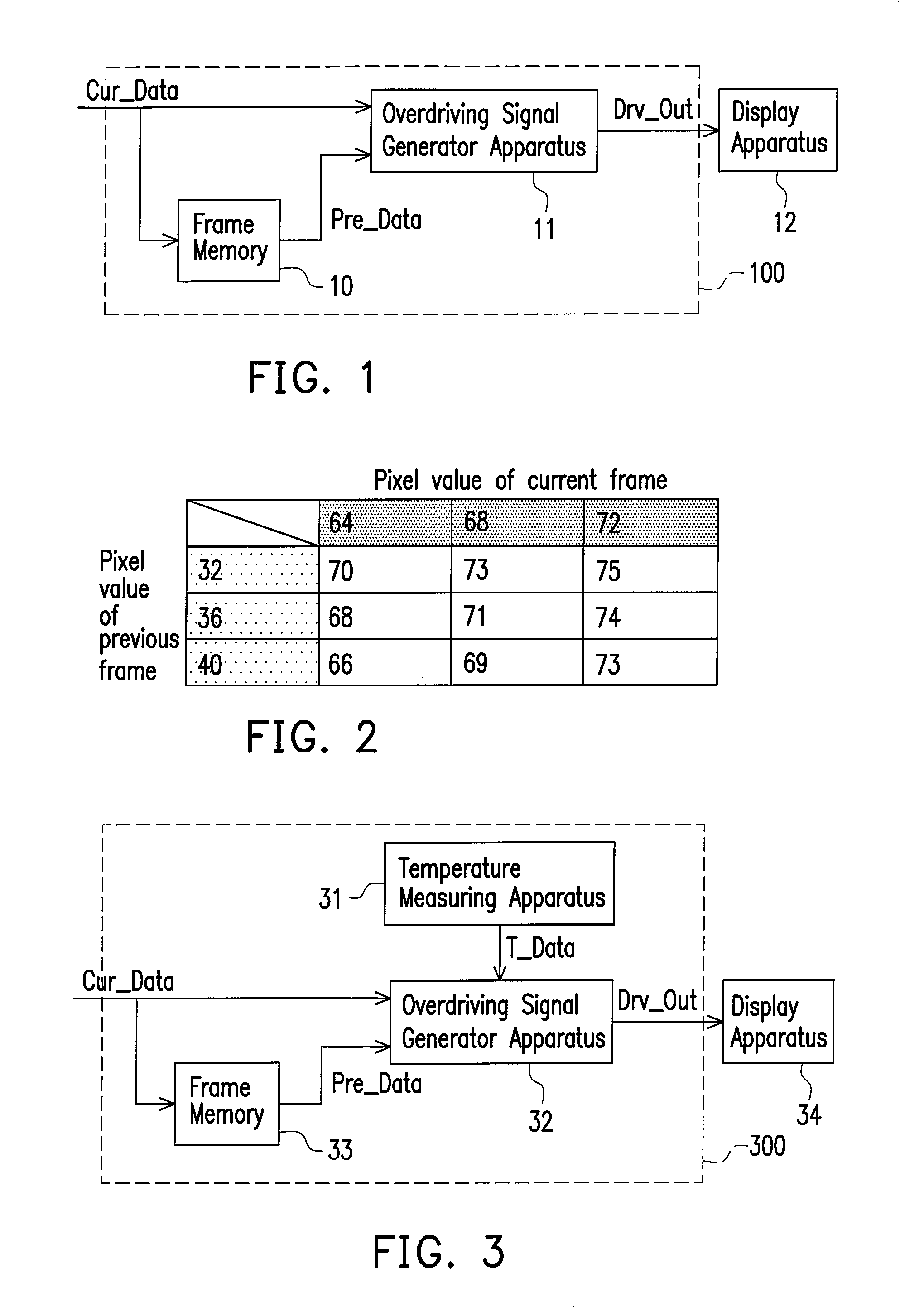
[0042]FIG. 3 is a circuit diagram of an overdriving apparatus 300 according to an embodiment of the present invention. The overdriving apparatus 300 includes a temperature measuring apparatus 31, an overdriving signal generator 32, and a frame memory 33. The temperature measuring apparatus 31 is coupled to the overdriving signal generator ...


PUM


Abstract

An overdriving apparatus and an overdriving method for a liquid crystal display (LCD) panel are disclosed. The overdriving apparatus includes a temperature measuring apparatus and an overdriving signal generator apparatus. The temperature measuring apparatus is coupled to the overdriving signal generator apparatus. The temperature measuring apparatus measures an operation temperature of the LCD panel. The overdriving signal generator apparatus generates a first overdriving signal according to a first image data of a current frame, x second image data of previous x frame(s), and the operation temperature, where x is a natural number.

Description

CROSS-REFERENCE TO RELATED APPLICATION[0001]This application claims the priority benefit of Taiwan application serial no. 97115365, filed on Apr. 25, 2008. The entirety of the above-mentioned patent application is hereby incorporated by reference herein and made a part of specification.BACKGROUND OF THE INVENTION[0002]1. Field of the Invention[0003]The present invention generally relates to an overdriving apparatus adapted for a display system, and a method thereof, and more particularly, to an overdriving apparatus for providing a compensation for the temperature influence.[0004]2. Description of Related Art[0005]Liquid crystal displays (LCD) have progressively replaced the conventional cathode ray tube (CRT) displays, because of their advantageous features such as smaller volume and lower power consumption. LCDs are employed in various kinds of products, from a small-sized panel for a cell phone screen to a large-sized for the television set and advertising viewing board. However,...

Claims


Application Information

Patent Timeline
IPC IPC(8): G09G3/36
CPCG09G3/3648G09G2340/16G09G2320/041G09G2320/0252
Inventor LO, JUI-LIN
Owner NOVATEK MICROELECTRONICS CORP
Learn More