Linear drive ultrasonic motor

a technology of ultrasonic motors and ultrasonic motors, applied in piezoelectric/electrostrictive/magnetostrictive devices, piezoelectric/electrostriction/magnetostriction machines, electrical apparatus, etc., can solve problems such as design limitation, and achieve the effect of stable pressing force and less restrictions on a relationship

Active Publication Date: 2009-10-29
OLYMPUS CORP
View PDF6 Cites 17 Cited by
  • Summary
  • Abstract
  • Description
  • Claims
  • Application Information

AI Technical Summary

Benefits of technology

[0008]The present invention is made in view of the abovementioned circumstances, and an object of the present invention is to provide a small-size linear drive ultrasonic motor which is capable of achieving a stable pressing force, and which has fewer restrictions regarding a relationship with an external apparatus.

Problems solved by technology

However, in the vibration apparatus described in Japanese Patent No. 3524248 Specification, when installed on some external apparatus, for avoiding a change in the pressing force of the pressing spring 905, there is a limitation of designing that the pressing spring 905 does not make a contact with a member of the external apparatus, in other words, that an arrangement is to be made to avoid the pressing spring 905.

Method used


Image

  • Linear drive ultrasonic motor
  • Linear drive ultrasonic motor
  • Linear drive ultrasonic motor

Examples


Embodiment Construction

[0021]In the following, embodiments of the linear drive ultrasonic motor according to the present invention will be described in detail with reference to the accompanying drawings. It should be understood that the present invention is not limited by the embodiments.

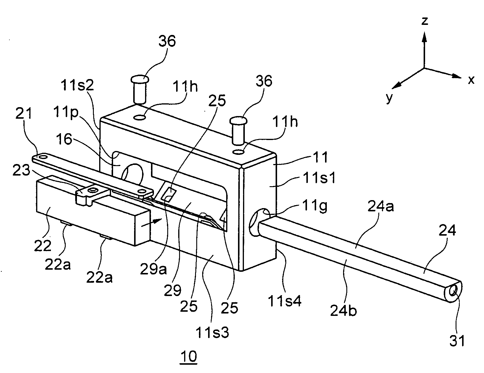
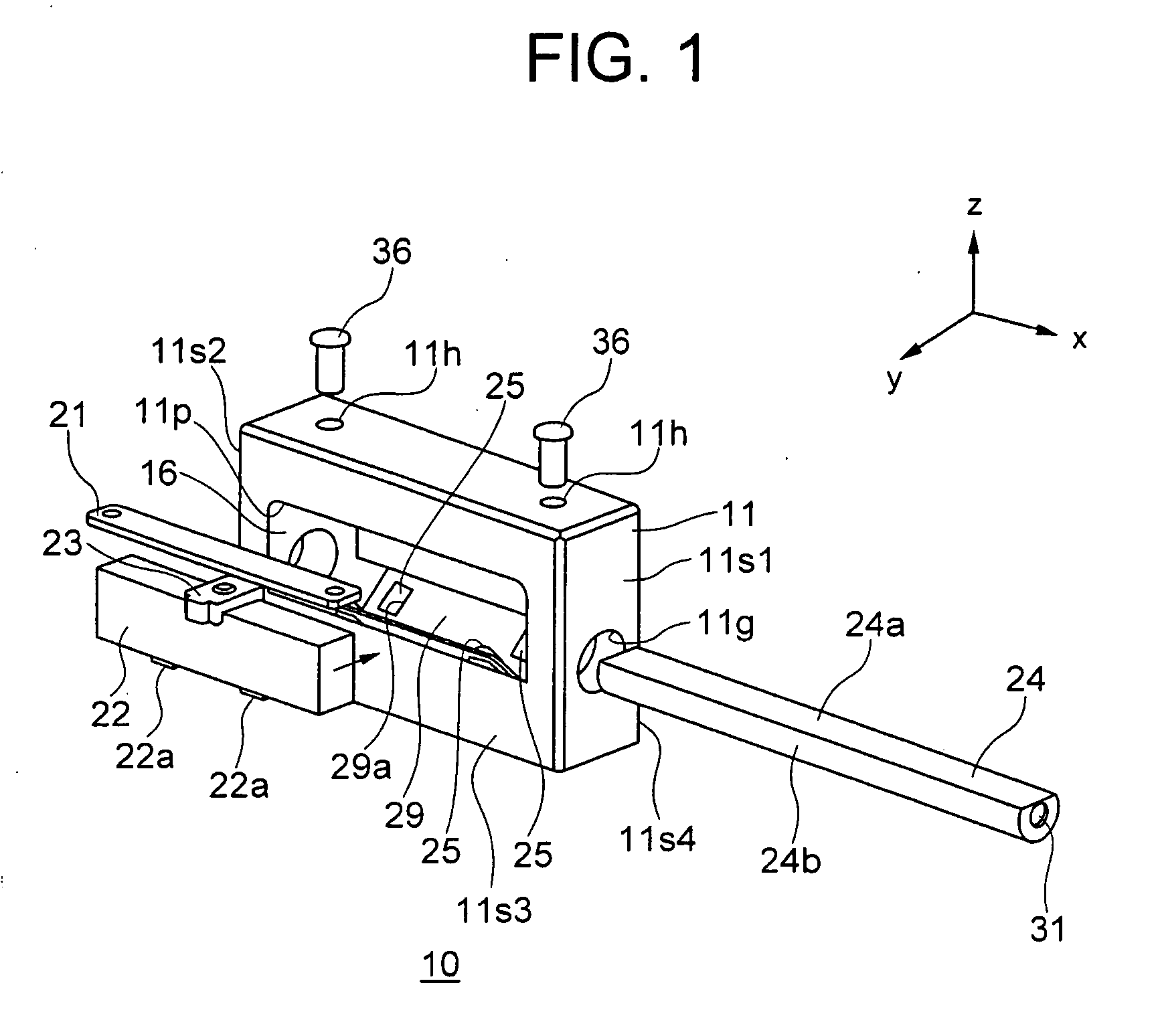
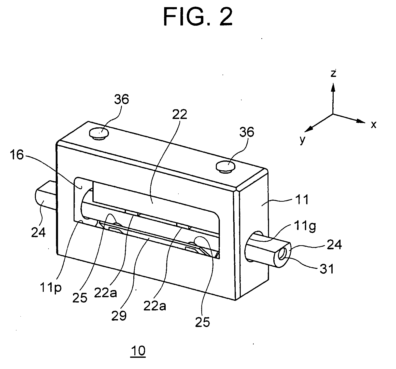
[0022]An ultrasonic motor 10 (linear drive ultrasonic motor) according to the embodiment of the present invention will be described below while referring to FIG. 1 and FIG. 2. However, the present invention is not restricted by the embodiment described below. Here, FIG. 1 is an exploded perspective view showing a structure of the ultrasonic motor 10, and FIG. 2 is a perspective view showing an outward appearance of the ultrasonic motor 10 in an assembled state.

[0023]As shown in FIG. 1, the ultrasonic motor 10 includes a vibrator 22 as an ultrasonic vibrator, a driven member 24, a pressing member 21, a case member 11, and rolling members 25 as a guiding mechanism. Each member will be described below in detail.

[0024]Both th...


PUM


Abstract

A linear drive ultrasonic motor includes at least an ultrasonic vibrator having a piezoelectric element, a driven member which is driven by a frictional force between the driven member and the ultrasonic vibrator, a pressing member which presses the ultrasonic vibrator such that a frictional force is generated between the ultrasonic vibrator and the driven member, a guiding mechanism which movably supports the driven member, and a case member which accommodates the ultrasonic vibrator, the pressing member, and the guiding means. The case member includes a first opening portion for making the driven member pass through, and a second opening portion which opens in a direction different from a direction in which the first opening portion opens and a direction of pressing by the pressing member.

Description

CROSS-REFERENCE TO RELATED APPLICATION[0001]The present application is based upon and claims the benefit of priority from the prior Japanese Patent Application No. 2008-114266 filed on Apr. 24, 2008; the entire contents of which are incorporated herein by reference.BACKGROUND OF THE INVENTION[0002]1. Field of the Invention[0003]The present invention relates to a linear drive ultrasonic motor.[0004]2. Description of the Related Art[0005]A vibration apparatus in Japanese Patent No. 3524248 Specification (FIGS. 3A and 3B) can be cited as an example of a conventional linear drive ultrasonic motor. Here, FIG. 3A and FIG. 3B are diagrams showing a structure of the conventional linear drive ultrasonic motor, where FIG. 3A is an exploded perspective view and FIG. 3B is a vertical cross-sectional view.[0006]The vibration apparatus shown in FIG. 3A and FIG. 3B includes a case 906 which accommodates a vibrating body 901, a mobile object 904 which passes through the case 906 and makes a contact...

Claims


Application Information

Patent Timeline
Patent Type & Authority Applications(United States)
IPC IPC(8): H02N2/04
CPCH02N2/04H02N2/026
Inventor TAKIZAWA, HIROYUKI
Owner OLYMPUS CORP
Why Eureka
Try Eureka