Eureka AIR delivers breakthrough ideas for toughest innovation challenges, trusted by R&D personnel around the world.

Method of seeking hydrocarbons in a geologically complex basin, by means of basin modeling

a geologically complex basin and basin modeling technology, applied in the field of methods, can solve the problems of affecting reliability, simple human assessment intervention is not sufficient to predict, and the current availability of basin simulators (softwares) is essentially limited

Active Publication Date: 2009-10-22
INST FR DU PETROLE
View PDF25 Cites 80 Cited by
  • Summary
  • Abstract
  • Description
  • Claims
  • Application Information

AI Technical Summary

Benefits of technology

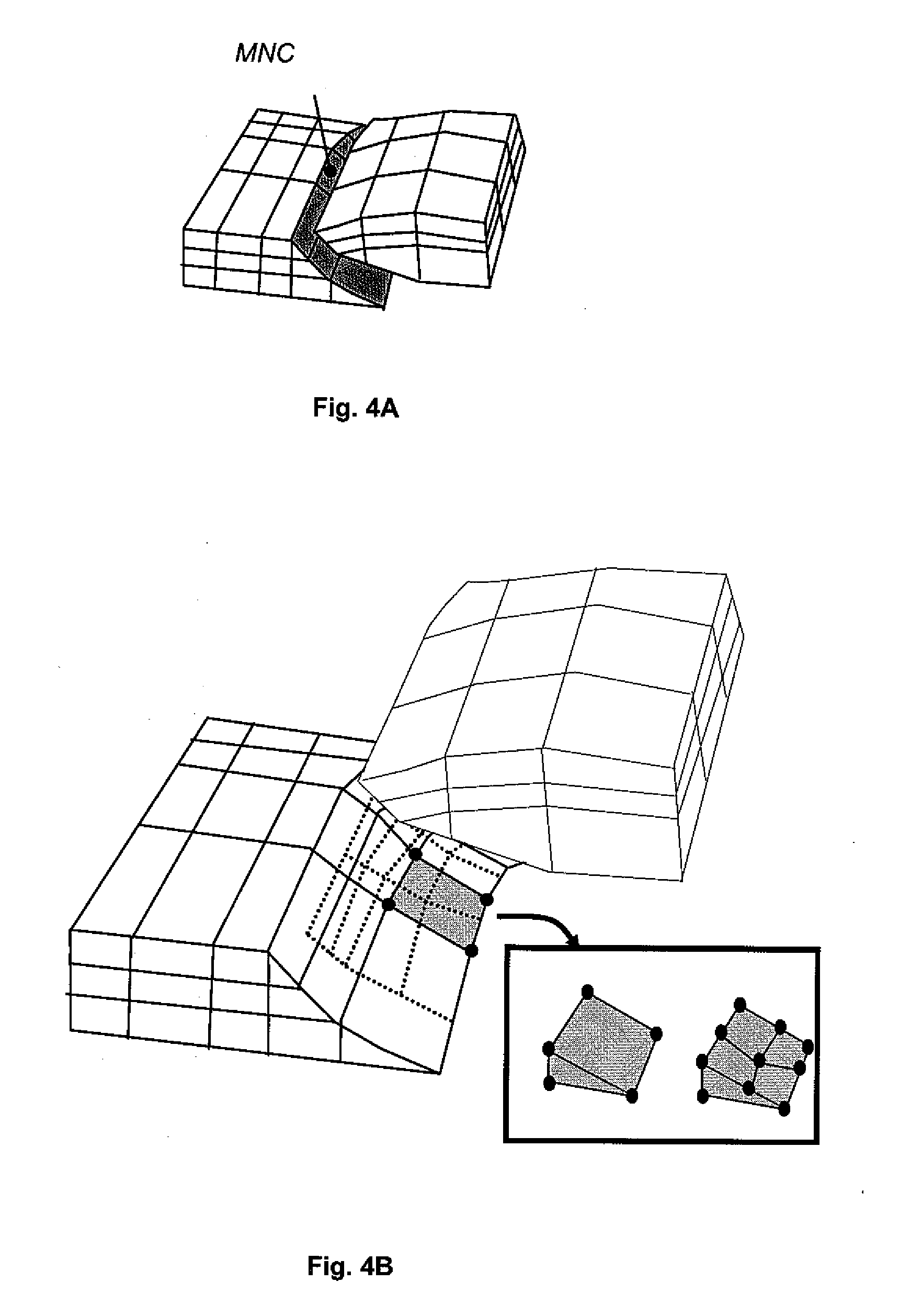
[0032]According to the invention, a subgrid can be constructed at the level of slip interfaces, such as faults or detachments, so that one face of a grid cell on one side of the interface is in contact with a single face of a cell located on the other side. It is also possible to supplement the Lagrangian grids with two layers of cells added along slip interfaces, by duplicating on each side of the interface the cells of the Lagrangian grid while ensuring coincidence of the cells on each side of the interface, and by assigning to the cells of the two layers a quasi-zero thickness, so as to take account of an anisotropic behaviour of the slip interfaces.

Problems solved by technology

In some sedimentary basins having a complicated geological history involving many physical processes, or when the volume of data is very large, a simple human assessment intervention is not sufficient to predict the location and the economic interest of reservoirs.
The basin simulators (softwares) currently available are essentially limited to the hypothesis that the deformation of the basin being studied is correctly represented by backstripping, that is all the deformations can be reasonably represented by vertical movements, without penalizing the reliability of the results.
However, many basins actually have a “complex” architecture and tectonic history for which this hypothesis is no longer acceptable; in this context, using a basin model in simple geometry can lead to errors on the prediction of traps.

Method used


Image

  • Method of seeking hydrocarbons in a geologically complex basin, by means of basin modeling
  • Method of seeking hydrocarbons in a geologically complex basin, by means of basin modeling
  • Method of seeking hydrocarbons in a geologically complex basin, by means of basin modeling

Examples


Embodiment Construction

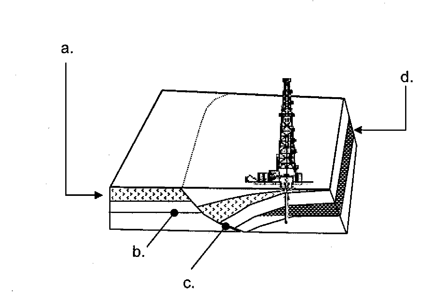
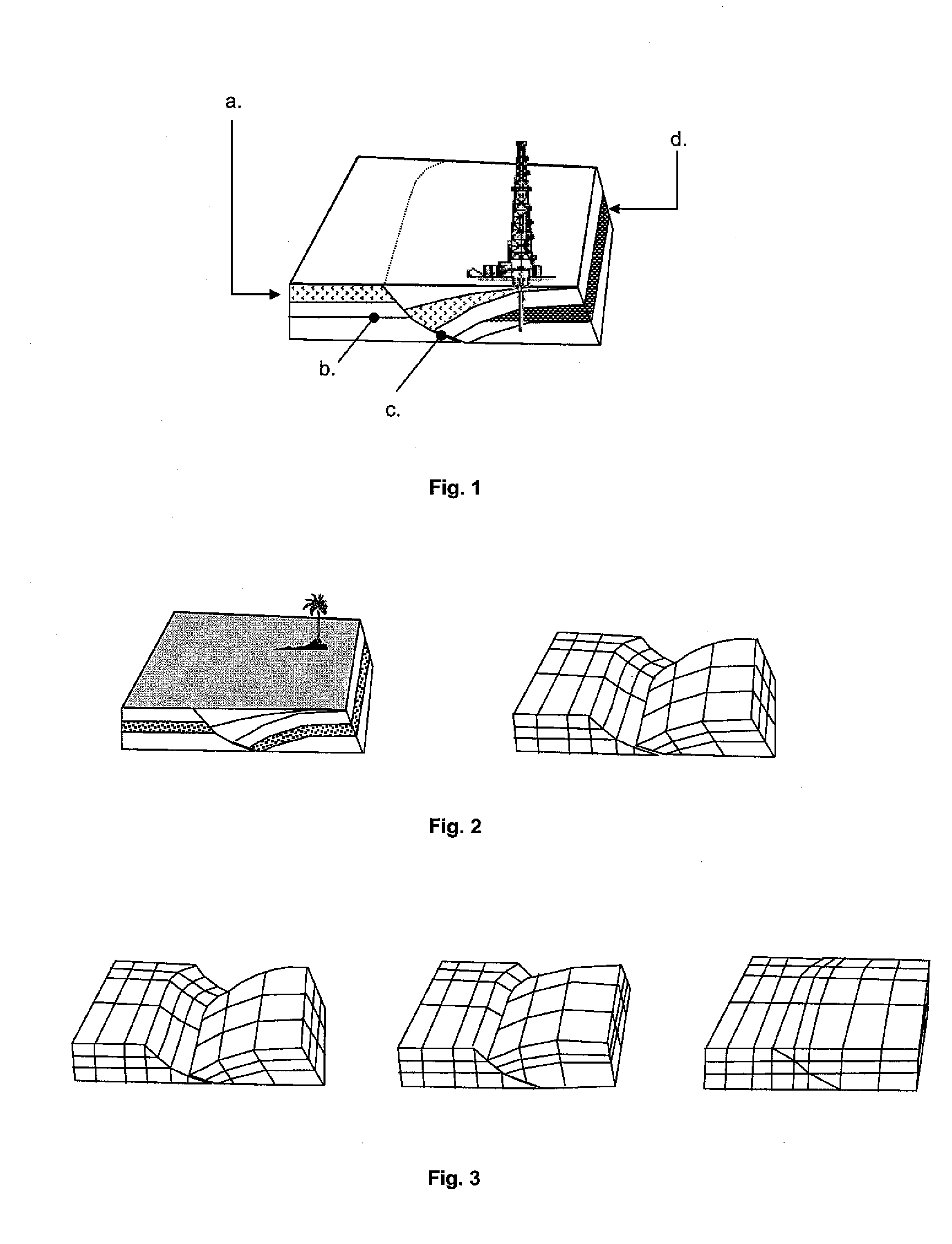
[0044]The method according to the invention allows mapping of a sedimentary basin comprising sedimentary layers and fractures. The architecture and the nature of the sedimentary layers of this basin, as they can be currently observed, result from a deformation of the subsoil over geological time, between a geological time t and the current time. FIG. 1 diagrammatically shows the subsoil of a petroleum basin, with:

[0045]a. a geological layer

[0046]b. a sedimentary interface

[0047]c. a fault surface (slip interface)

[0048]d. a hydrocarbon accumulation in a geological layer.

[0049]The method comprises a typically three-dimensional basin modeling technique applicable to the search for petroleum traps in complex tectonic contexts. It comprises the following three stages:

[0050]1. A stage of construction of a grid of the sedimentary basin, as it is assumed to be today. This grid is kept for the next two stages;

[0051]2. A stage of three-dimensional restoration based on the aforementioned grid, ...


PUM


Abstract

A method for mapping a complex sedimentary basin is disclosed. A grid representative of the current architecture of the basin is constructed. A mechanical structural restoration is applied in three dimensions so as to reconstruct the past architectures of the basin from the current time up to a geological time t. A simulation of the geological and geochemical processes that govern the formation of a petroleum reservoir is then carried out, directly in the grids obtained from the restoration, from the geological time t to the current one. This simulation is thereafter used for mapping the sedimentary basin so as to identify zones of the basin where hydrocarbons may have accumulated.

Description

BACKGROUND OF THE INVENTION[0001]1. Field of the Invention[0002]The present invention relates to the field of petroleum exploration. Petroleum exploration consists in seeking hydrocarbon reservoirs in a sedimentary basin.[0003]2. Description of the Prior Art[0004]The general procedure comprises:[0005]assessments and geological studies for evaluating the petroleum potential of the sedimentary basin, from available data (outcrops, seismic surveys, drilling data). The goal of this assessment is to:[0006]better understand the architecture and the geological history of the subsoil, notably to study whether hydrocarbon maturation and migration processes may have taken place;[0007]identify the subsoil zones where these hydrocarbons may have accumulated;[0008]establish which zones have the best economic potential, evaluated from the volume and the nature of the hydrocarbons probably trapped (viscosity, rate of mixing with water, chemical composition, . . . ), as well as their operating cost...

Claims


Application Information

Patent Timeline
Patent Type & Authority Applications(United States)
IPC IPC(8): G06G7/48G01V9/00
CPCG01V99/00
Inventor CACAS, MARIE-CHRISTINERUDKIEWICZ, JEAN-LUCFAILLE, ISABELLEDANIEL, JEAN-MARCHAVE, PASCAL
Owner INST FR DU PETROLE
Why Eureka
Eureka Blog
Learn More