
Swath line creation including slope compensation for an automatic guidance system of a work vehicle

a technology of automatic guidance system and swath line, which is applied in the direction of distance measurement, navigation instruments, instruments, etc., can solve the problems of overlap of swaths or gaps between swaths, and achieve the effect of reducing operator fatigue and increasing the accuracy of the path of the vehicl

Active Publication Date: 2009-10-22
BLUE LEAF I P
View PDF13 Cites 28 Cited by
  • Summary
  • Abstract
  • Description
  • Claims
  • Application Information

AI Technical Summary

Benefits of technology

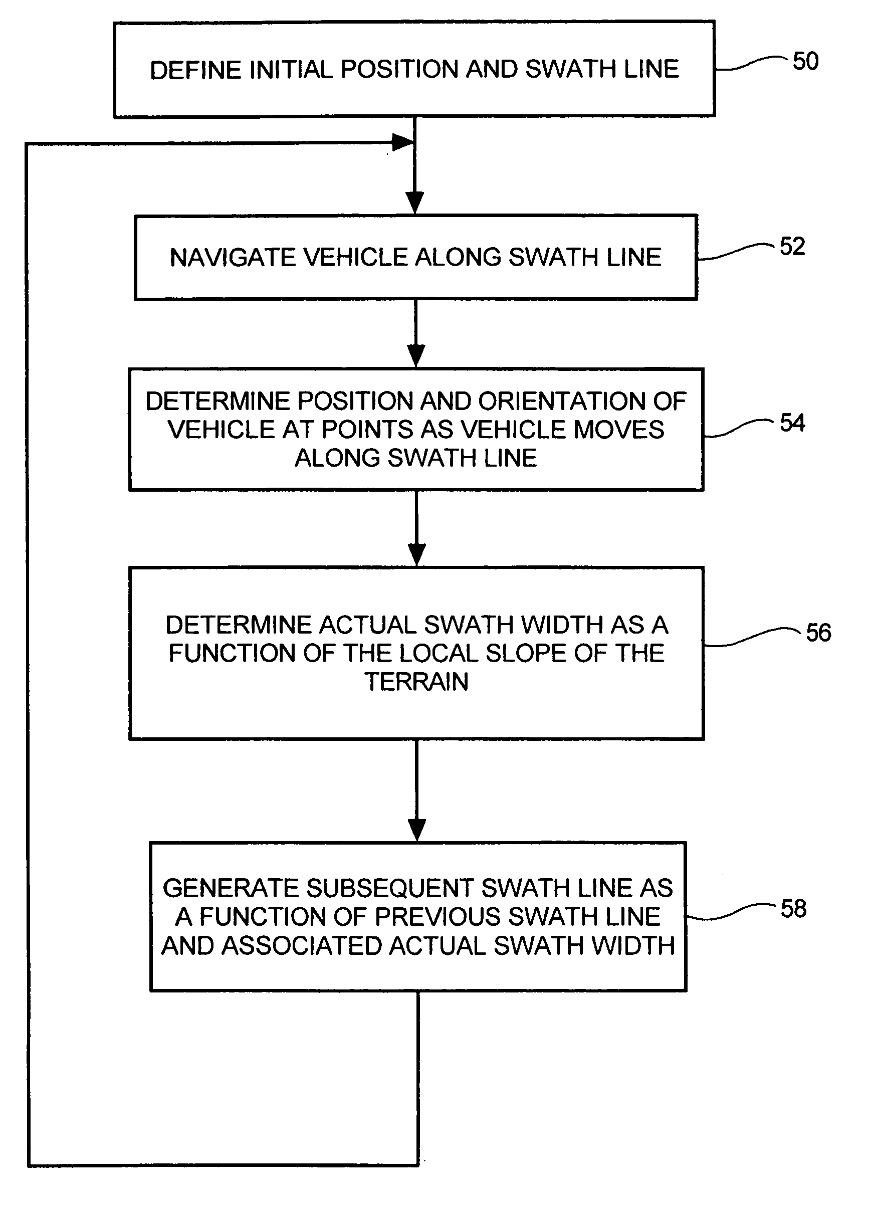
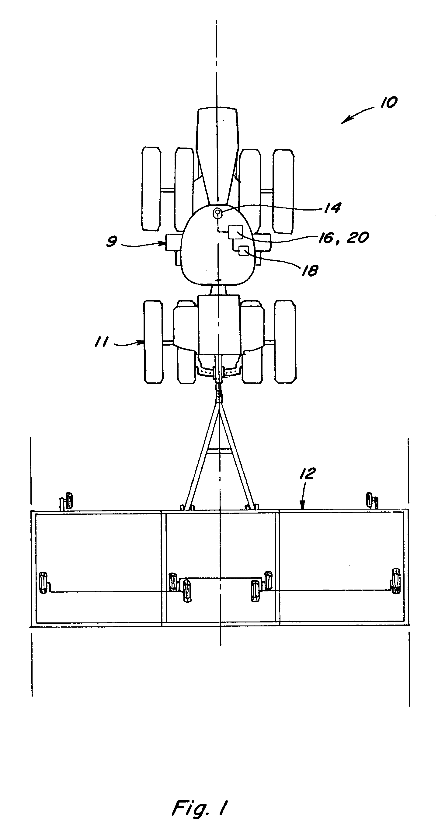
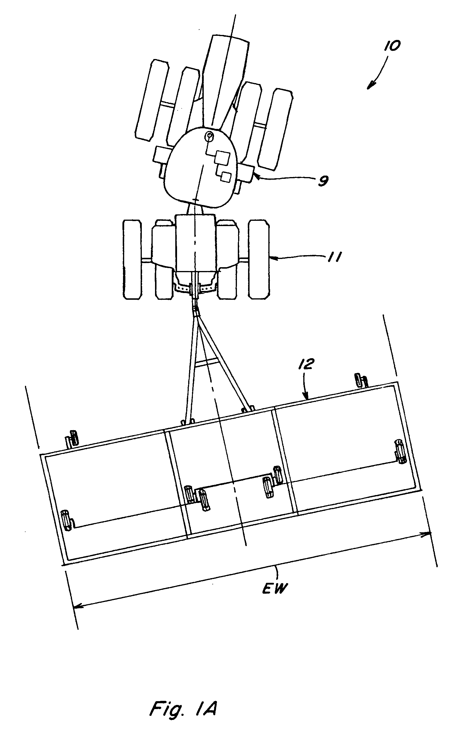
[0009]What is disclosed is an apparatus and method to generate swath lines and swath patterns that include swath corrections to compensate for variations in the slope of a field which overcomes at least one of the problems, shortcomings or disadvantages set forth above. Automatic guidance systems based on Global Positioning Satellite (GPS) information have gained widespread use in work vehicles such as tractors. These systems automatically steer the tractor to follow predetermined swath lines limiting the need for the operator to steer. Thus, operator fatigue may be reduced, and the accuracy of the path of the vehicle may be increased. It is common, however, that the vehicle must be manually turned at the end of the row. Swath lines are typically generated by recording initial position data of the vehicle, defining an initial swath line, and generating additional swath lines for the vehicle. For example, after recording the position of the vehicle, the operator may record two points defining a straight line or more than two points defining a curve as an initial swath line. A swath generating apparatus then automatically generates additional rows or swaths across the field. Typically these swath lines are generated with constant spacing based on the width of the element coupled with the work vehicle. Usually the constant spacing is calculated with respect to a plane tangent to the surface of the earth. When the work vehicle is operating on sloped terrain, however, calculation of swath lines based on the width of the element may lead to overlap of swaths or gaps between swaths that are not reached by the element.
[0010]According to an aspect of the present invention, swath lines are generated to compensate for the slope of the field and reduce the gaps between swaths that are not reached by the element coupled to the work machine. The swath lines are generated as the operator traverses the field so the operator may work in the field with less preplanning or preparation. An initial swath line is recorded by the operator along with an initial position of the vehicle. As the vehicle traverses the initial swath line, the spatial position and roll, if available, of the vehicle with respect to the direction of travel is determined. Prior to its initiation, a subsequent swath line is generated as a function of the spatial position and / or roll of the vehicle as it traversed an earlier, or in this case, the initial swath line. In a similar manner further subsequent swath lines are generated based on the spatial position and roll of the vehicle determined as it traversed the earlier swath line. It is preferable for the operator to drive swaths adjacent to or relatively close to previous paths so that the slope information will be more accurate.
[0011]According to another aspect of the present invention, swath lines are generated to compensate for the slope of the field and reduce the gaps between swaths that are not reached by the element coupled to the work machine prior to operating in the field based on topographical data that may be obtained from sources such as, but not limited to, topographical maps including elevation, aerial photographs, data obtained from driving the field with a GPS receiver, or a combination of sources. The operator defines an initial swath line and additional swath lines are generated as a function of the topographical data associated with the field. In addition, the field may be divided into patches, each patch having a defined initial swath line and additional swath lines generated as a function of the topographical data associated with that patch. Because the swath lines and swath pattern is preplanned for the entire field, the operator is free to work the field driving swaths in any particular order.

Problems solved by technology

When the work vehicle is operating on sloped terrain, however, calculation of swath lines based on the width of the element may lead to overlap of swaths or gaps between swaths that are not reached by the element.

Method used


Image

  • Swath line creation including slope compensation for an automatic guidance system of a work vehicle
  • Swath line creation including slope compensation for an automatic guidance system of a work vehicle
  • Swath line creation including slope compensation for an automatic guidance system of a work vehicle

Examples


Embodiment Construction

[0023]The swath generation apparatus and methods described herein may find application in precision agriculture systems used to control crop spraying operations, harvesting operations, cultivation and plowing operations, planting and seeding operations, fertilizer application, or other operations where highly accurate positioning information is used in conjunction with defined patterns of swaths to control transit of a vehicle over a land area. Such systems for precision location determination are generally well known and are exemplified by those disclosed in U.S. Pat. Nos. 6,199,000 and 6,553,299, each entitled “Methods and Apparatus for Precision Agriculture Operations Using Real Time Kinematic Global Positioning Systems” which are incorporated herein in their entirety by reference. Although the various methods will be described with particular reference to GPS based systems, it should be appreciated that the teachings are equally applicable to control systems using other methods ...


PUM


Abstract

An apparatus and method for generating swath lines including compensation for sloping terrain in a field for use in an automatic guidance system of a work machine. The swath lines are created as a function of the position, elevation and / or orientation of the work vehicle.

Description

TECHNICAL FIELD[0001]The present invention relates generally to apparatus and methods for GPS based vehicle guidance systems and more particularly to a method and apparatus for generating swath lines that compensate for error introduced when a swath line is located on a sloped portion of a field.BACKGROUND ART[0002]Off road work vehicles in the agricultural, mining and construction fields, such as tractors, and the like, have traditionally operated with manual steering. Improvements in control system design and related position sensing technology, such as global positioning systems (GPS), including differential correction systems, as well as real time kinematic (RTK) satellite navigation have led to an increase in the use of automatic guidance control systems for these vehicles. The combination of improved navigation input signals precisely identifying vehicle position and speed with sophisticated on board vehicle electronic control systems allows for automatic guidance systems capa...

Claims


Application Information

Patent Timeline
IPC IPC(8): G01C21/00G01S5/14
CPCA01B69/008G01S19/38G05D1/0219G05D2201/0201G05D1/0274G05D1/0278G05D1/027
Inventor DIX, PETER J.
Owner BLUE LEAF I P
Learn More