
Diaphragm driving device of a camera system using an interchangeable lens

a technology of diaphragm drive and interchangeable lens, which is applied in the field of diaphragm drive device of camera system, can solve the problems of general versatility, increased power consumption of driving unnecessary increase in power consumption, so as to reduce the driving current, and reduce the power consumption of the diaphragm drive motor

Inactive Publication Date: 2009-10-22
RICOH IMAGING COMPANY
View PDF14 Cites 15 Cited by
  • Summary
  • Abstract
  • Description
  • Claims
  • Application Information

AI Technical Summary

Benefits of technology

[0011]It is desirable for the diaphragm mechanism of the interchangeable lens to include a diaphragm control bar for changing an aperture size by a movement of the diaphragm control bar, wherein the diaphragm driving device provided in the camera body includes a diaphragm-driving slide plate which engages with the diaphragm control bar when the interchangeable lens is attached to the camera body. The in-lens spring device includes a control-bar restoring spring which moves the diaphragm control bar in the stop-down direction to make the diaphragm mechanism of the interchangeable lens perform the stop-down operation. The diaphragm drive motor drives the diaphragm-driving slide plate in the stop-down direction so as to move the diaphragm control bar in the stop-down direction thereof. The in-body spring device includes a diaphragm-driving slide plate restoring spring which biases the diaphragm-driving slide plate in a direction to increase the aperture size to a maximum.
[0019]According to the present invention, by controlling the torque of the diaphragm drive motor in accordance with the spring force of the in-lens spring device when the operation of the diaphragm mechanism is controlled in the interchangeable lens, the driving current for the diaphragm drive motor can be controlled in order to compensate for a different spring force of the in-lens spring device that differs depending on the type of interchangeable lens, which makes it possible to achieve a reduction in power consumption of the diaphragm drive motor by reducing the driving current therefor. Specifically, by making the spring force of the in-lens spring device and the torque of the diaphragm drive motor act in the same direction, the power consumption of the diaphragm drive motor is reduced by reducing the driving current for the diaphragm drive motor when the spring force of the in-lens spring device is great. For instance, by configuring the diaphragm driving device so that the in-lens spring device and the diaphragm drive motor operate in a direction to stop down the diaphragm, the torque of the diaphragm drive motor can be reduced during the stopping-down operation when the spring force of the in-lens spring device is great, which makes it possible to achieve a reduction in power consumption of the diaphragm drive motor.

Problems solved by technology

The diaphragm driving device shown in JUPP 2002-290828 is required to be equipped with a mechanism for coupling a diaphragm drive motor installed in the camera body to a stop-down mechanism installed in the interchangeable lens, and therefore cannot be applied to an interchangeable lens equipped with a conventional diaphragm control bar, thus having a problem with general versatility.
On the other hand, the diaphragm driving device which stops down the diaphragm of the interchangeable lens by a conventional diaphragm-driving slide plate excels in general versatility with interchangeable lenses, but there is a problem with the power consumption for driving the diaphragm drive motor increasing since the diaphragm-driving slide plate, provided in the camera body for driving the diaphragm control bar installed in the interchangeable lens, is driven by a rotational force of the diaphragm drive motor (stepping motor).
Therefore, if the spring force of the control-bar restoring spring is great, the electrical power which is supplied to the stepping motor becomes greater than necessary, which results in an unnecessary increase in power consumption.

Method used


Image

  • Diaphragm driving device of a camera system using an interchangeable lens
  • Diaphragm driving device of a camera system using an interchangeable lens
  • Diaphragm driving device of a camera system using an interchangeable lens

Examples


Embodiment Construction

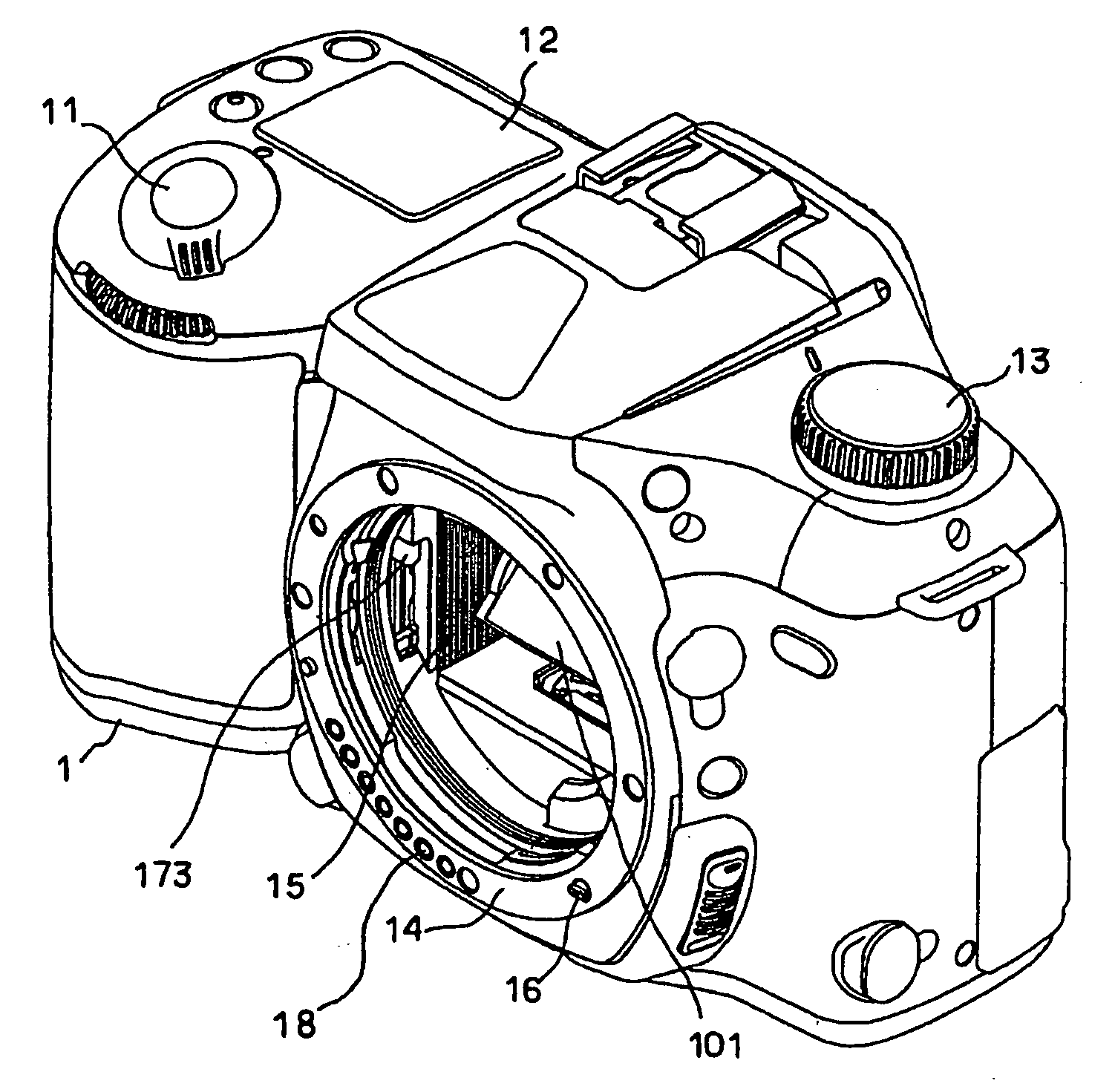
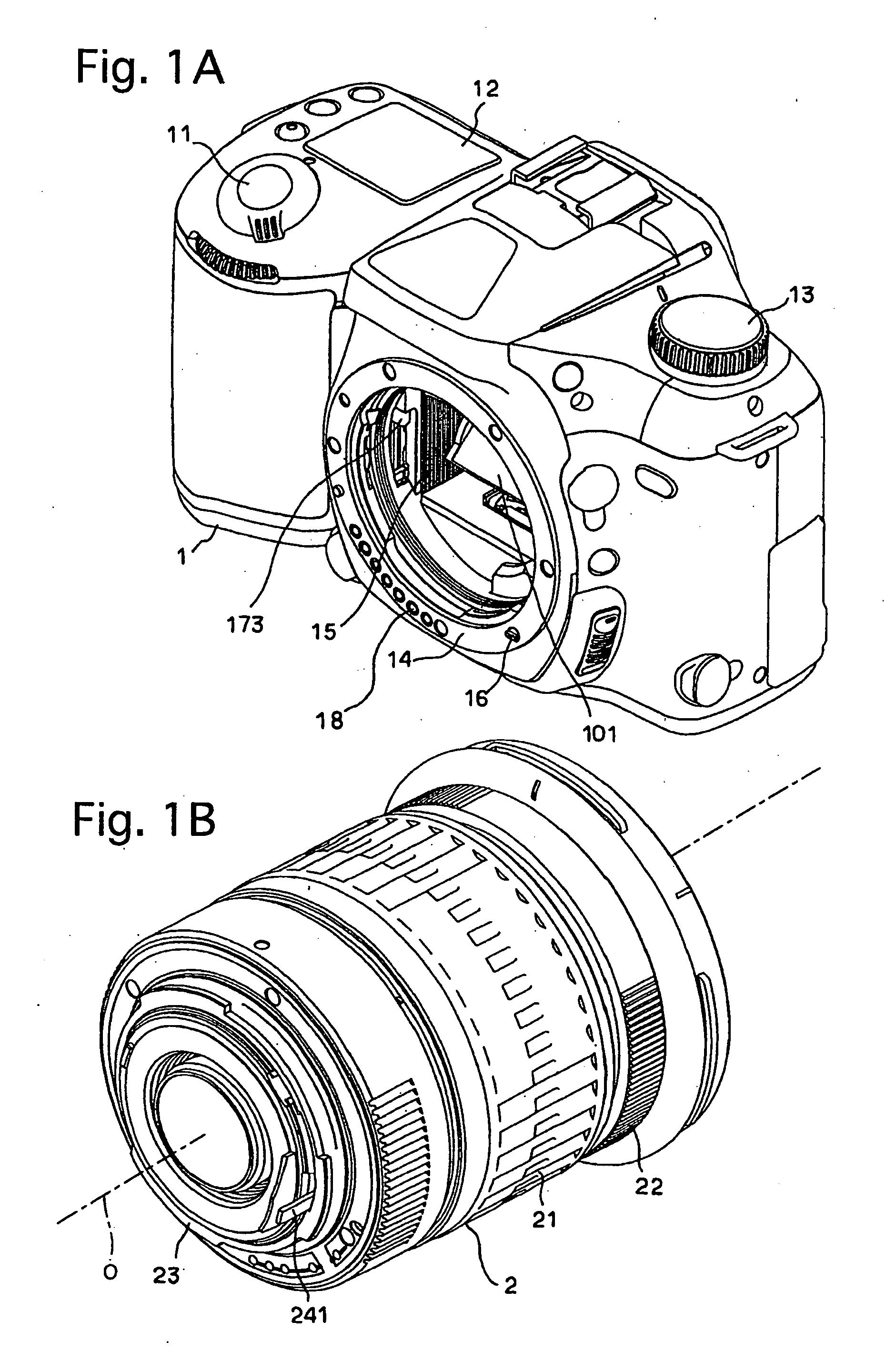
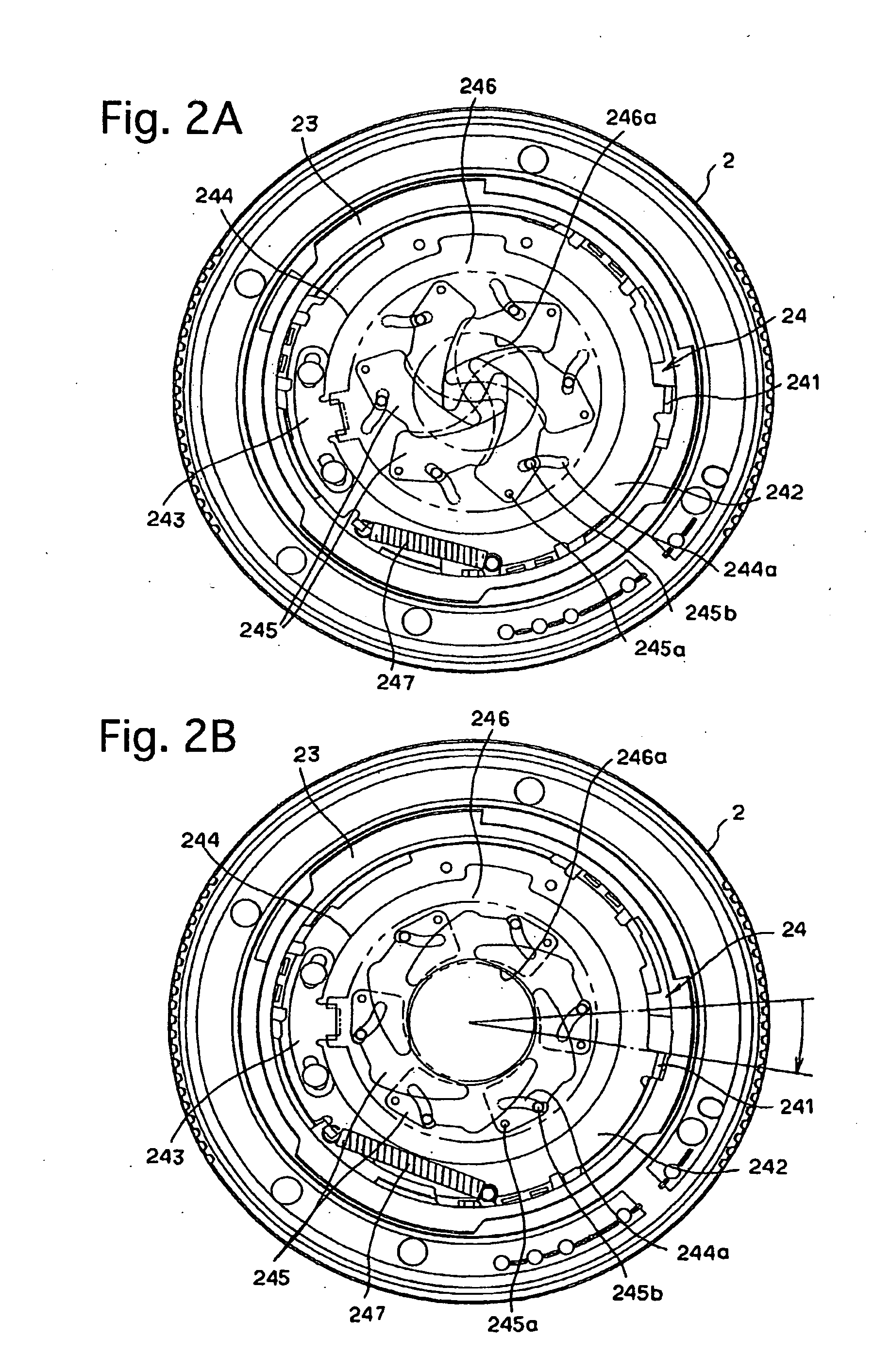
[0035]FIG. 1A is a front perspective view of a camera body 1 of an embodiment of an SLR digital camera system according to the present invention, and FIG. 1B is a rear perspective view of an interchangeable lens 2 of the SLR camera system which includes a diaphragm control bar 241. As shown in FIG. 1A, the camera body 1 is provided with a release button (photometering switch / release switch) 11, an LCD indicator 12 and a mode select dial 13. The camera body 1 is provided on the front thereof with a lens mount 14 to which the interchangeable lens 2 is detachably attached. The camera body 1 is provided therein with a mirror box 15 which is exposed at the lens mount 14, and is provided in the mirror box 15 with a main mirror (quick-return mirror) 101 and a diaphragm-driving slide plate 173 which is slidingly moved upwards with respect to FIG. 1A upon the main mirror 101 rising. The camera body 1 is provided on part of the lens mount 14 with an AF coupler 16 for performing an AF control ...


PUM


Abstract

A diaphragm driving device for a camera including a camera body and an interchangeable lens which is detachably attached to the camera body, wherein the interchangeable lens includes a diaphragm mechanism having an in-lens spring device for performing a stop-down operation, the in-lens-spring device having a spring constant. The camera body includes a diaphragm drive mechanism having a diaphragm drive motor and an in-body spring device, both of which are for making the diaphragm mechanism of the interchangeable lens perform the stop-down operation, anda controller for controlling a driving current which is supplied to the diaphragm drive motor in accordance with the spring constant of the in-lens spring device.

Description

BACKGROUND OF THE INVENTION[0001]1. Field of the Invention[0002]The present invention relates to a camera system such as an SLR camera system which includes a camera body and an interchangeable lens that is detachably attached to the camera body, and in particular relates to a diaphragm driving device of the camera system which is configured so that the operation of an adjustable diaphragm of the interchangeable lens is controlled by the camera body.[0003]2. Description of the Prior Art[0004]In conventional camera systems using an interchangeable photographic lens (hereinafter referred to as an interchangeable lens), especially in SLR camera systems, upon taking a picture, the main mirror (quick-return mirror) is raised so that it retracts from a photographing optical path while a diaphragm drive mechanism in the camera body is actuated to stop down a diaphragm (iris diaphragm) to the position of a preset F-number from a full-aperture state, and thereupon, the shutter (focal-plane s...

Claims


Application Information

Patent Timeline
IPC IPC(8): G03B9/02
CPCG03B9/02
Inventor KUROSAWA, YUICHI
Owner RICOH IMAGING COMPANY
Learn More