
Wireless Resource Allocation Method In Wireless Communication System And Wireless Base Station In The Same

a wireless communication system and resource allocation technology, applied in the direction of wireless communication, wireless commuication services, electrical equipment, etc., can solve the problems of bs not being able to transmit (respond) the response signal, delay the start of communication, etc., to achieve the effect of more effective wireless resource allocation

Inactive Publication Date: 2009-10-22
FUJITSU LTD
View PDF6 Cites 16 Cited by
  • Summary
  • Abstract
  • Description
  • Claims
  • Application Information

AI Technical Summary

Benefits of technology

The present invention provides a wireless resource allocation method in a wireless communication system having a plurality of wireless terminals and at least one wireless base station communicating with the plural wireless terminals. The method includes monitoring a state of reception of specific signals transmitted by the wireless terminals, determining whether to execute the wireless resource allocation based on priority beforehand set to each of the wireless terminals, and allocating the wireless resource based on the priority when the priority is determined to be executed. This allows for preferential allocation of wireless resource to users with higher priority, even in a situation where a plurality of wireless terminals simultaneously start communications, and delays the start of communication.

Problems solved by technology

When users of MSs are in a crowded place or a disaster occurs, it could happen that the MSs connecting to the BS simultaneously start communications.
However, it could take a time to allocate the wireless resource to such a user although his / her priority is higher than those of the others, which delays the start of the communication.
However, there is possibility that the BS cannot transmit (respond) the response signal to all the CDMA codes received from the MSs because the wireless resource is limited.

Method used


Image

  • Wireless Resource Allocation Method In Wireless Communication System And Wireless Base Station In The Same
  • Wireless Resource Allocation Method In Wireless Communication System And Wireless Base Station In The Same
  • Wireless Resource Allocation Method In Wireless Communication System And Wireless Base Station In The Same

Examples


Embodiment Construction

[0114]Hereinafter, description will be made of embodiments of the present invention with reference to the drawings. Note that the present invention is not limited to embodiments and modifications to be described hereinafter, but modification may be made in various ways without departing from the spirit and scope of the invention.

[A] Description of Embodiment

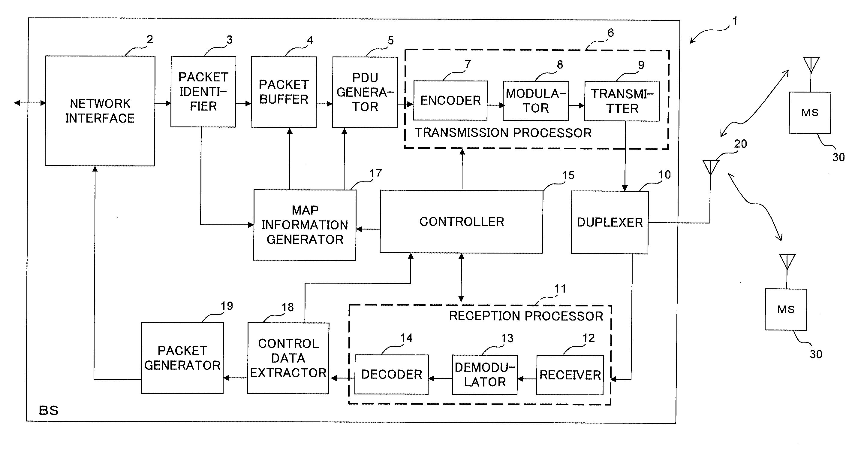
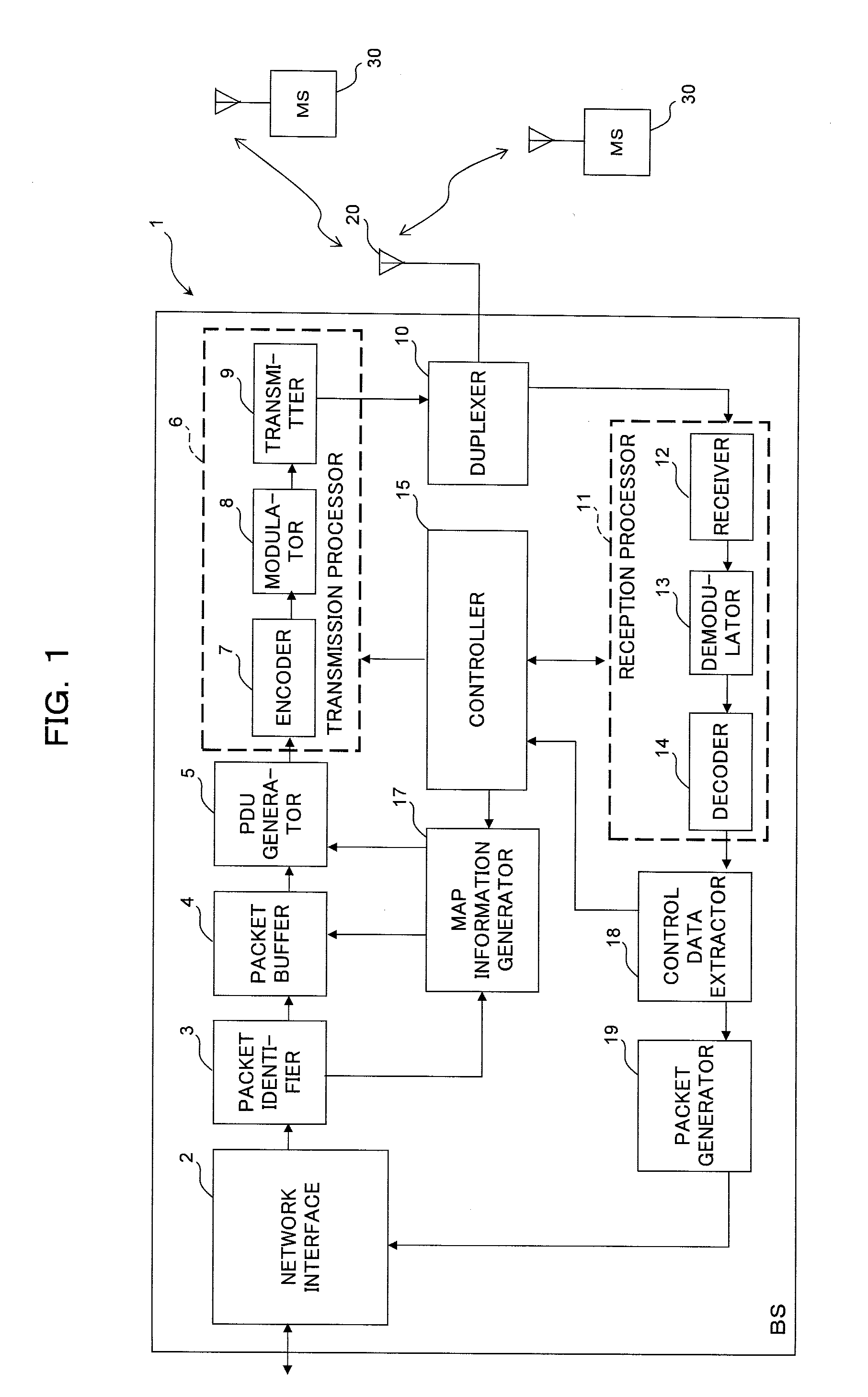
[0115]FIG. 1 is a block diagram illustrating a configuration of essential part of a wireless base station (BS) in a wireless communication system according to an embodiment of this invention. The BS 1 illustrated in FIG. 1 communicates with a plurality of wireless terminals (MS) 30 by radio. A wireless frame used in this wireless communication is premised on a wireless frame in conformity to IEEE802.16e standard aforementioned with reference to FIG. 13, for example.

[0116]The MS 30 transmits, to the BS1, a specific signal (CDMA code) for obtaining a right to transmit a request for wireless resource allocation, that is, a request f...


PUM


Abstract

A wireless base station monitors a state of reception in a common transmission region (channel) in a wireless frame common to a plurality of wireless terminals, and controls allocation of a transmission region in the wireless frame to be used for transmission by the wireless terminals on the basis of a result of the monitoring and information about priority set to each of the plural wireless terminals. The wireless resource can be preferentially allocated to a wireless terminal of a user having high priority even when the common communication region used to obtain permission to send a bandwidth request is congested.

Description

CROSS-REFERENCE TO RELATED APPLICATION[0001]This application is a continuation Application of a PCT international application No. PCT / JP2007 / 051715 filed on Feb. 1, 2007 in Japan, the entire contents of which are incorporated by reference.TECHNICAL FIELD[0002]The present invention relates to a wireless resource allocation method in a wireless communication system and a wireless base station in the same.BACKGROUND ART[0003]In a wireless communication system having a wireless base station (BS) and a wireless terminal (for example, a mobile station) (MS), the MS can communicate with another MS via the BS.[0004]In such a wireless communication system, there is generally provided QoS (Quality of Service) that reserves a bandwidth for a specific communication and assures a certain transmission speed.[0005]The QoS realizes a communication based on priority for each user according to information (contract information, etc.) about the user possessing the MS, for example. The Qos can provide ...

Claims


Application Information

Patent Timeline
Patent Type & Authority Applications(United States)
IPC IPC(8): H04W72/04H04W72/54
CPCH04W72/10H04W72/56
Inventor SUGA, JUNICHI
Owner FUJITSU LTD
Learn More