
Optical drive with improved laser power control (LPC)

a technology of optical drive and laser power control, which is applied in the direction of optical beam sources, recording signal processing, instruments, etc., can solve the problems of not being able to continuously monitor the actual laser, not being able to achieve the stability and efficiency of forward sense control, etc., to facilitate the implementation of a write strategy and reduce the time spent on re-calibration

Inactive Publication Date: 2009-10-22
KONINKLIJKE PHILIPS ELECTRONICS NV
View PDF13 Cites 0 Cited by
  • Summary
  • Abstract
  • Description
  • Claims
  • Application Information

AI Technical Summary

Benefits of technology

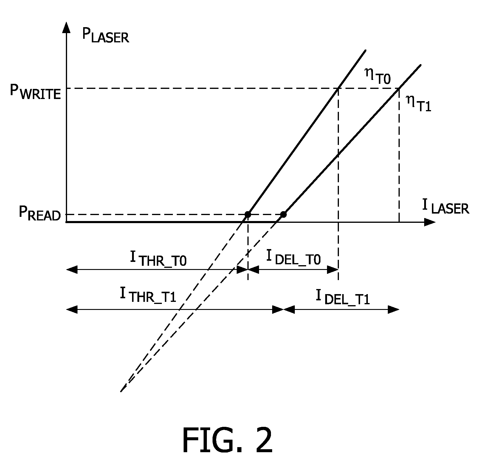
[0016]The invention is particularly, but not exclusively, advantageous for obtaining a simple and fast solution capable of compensating, in an efficient manner, drift in the characteristic response of the radiation source of the optical drive because the re-calibration of the present invention can be performed by refining or re-adapting the change current during operation of the optical drive. It is a distinct advantage of the present invention that the re-calibration of the change current can be performed with no or very little time consumption as compared to the prior art, in particular WO 2004 / 105004, as the re-calibration can be performed during e.g. a writing process of the optical drive. Additionally, the delicate fine-tuning of the change current that is possible with the present invention is particularly suited for multiple power level write strategies with high requirements on the precision and repeatability of the applied power levels. Such write strategies are more and more commonly applied in the field of optical drives.

Problems solved by technology

Alternatively, laser power control (LPC) could be performed by test writing in dedicated power calibration areas (PCA) on the disc in the same regions where “optimum power control” (OPC) is also performed, but this is an open-loop / feed-forward method and it is not as stable and efficient as forward sense (FS) control.
The feedback control in principle thereby enables a continuous monitoring of the laser power, but due to the relatively high level of laser power and / or the fast alternation of the laser power due the write strategy applied, it is not possible to continuously monitor the actual laser power, and accordingly various models predicting the actual behavior of the laser under e.g. higher power can be applied to remedy this shortcoming of the forward sense (FS) method.
A disadvantage of this solution is therefore that at least two different thresholds have to be found for the laser which necessitates a considerable use of time due to cooling or heating of the laser and therefore reading or writing can not take place during the re-calibration.

Method used


Image

  • Optical drive with improved laser power control (LPC)
  • Optical drive with improved laser power control (LPC)
  • Optical drive with improved laser power control (LPC)

Examples


Embodiment Construction

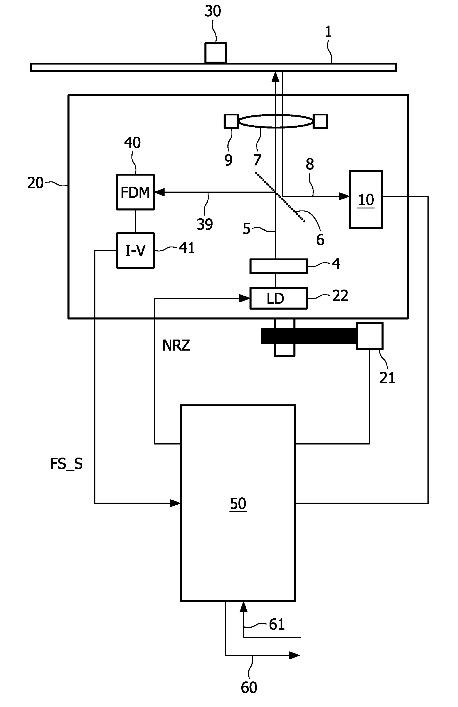
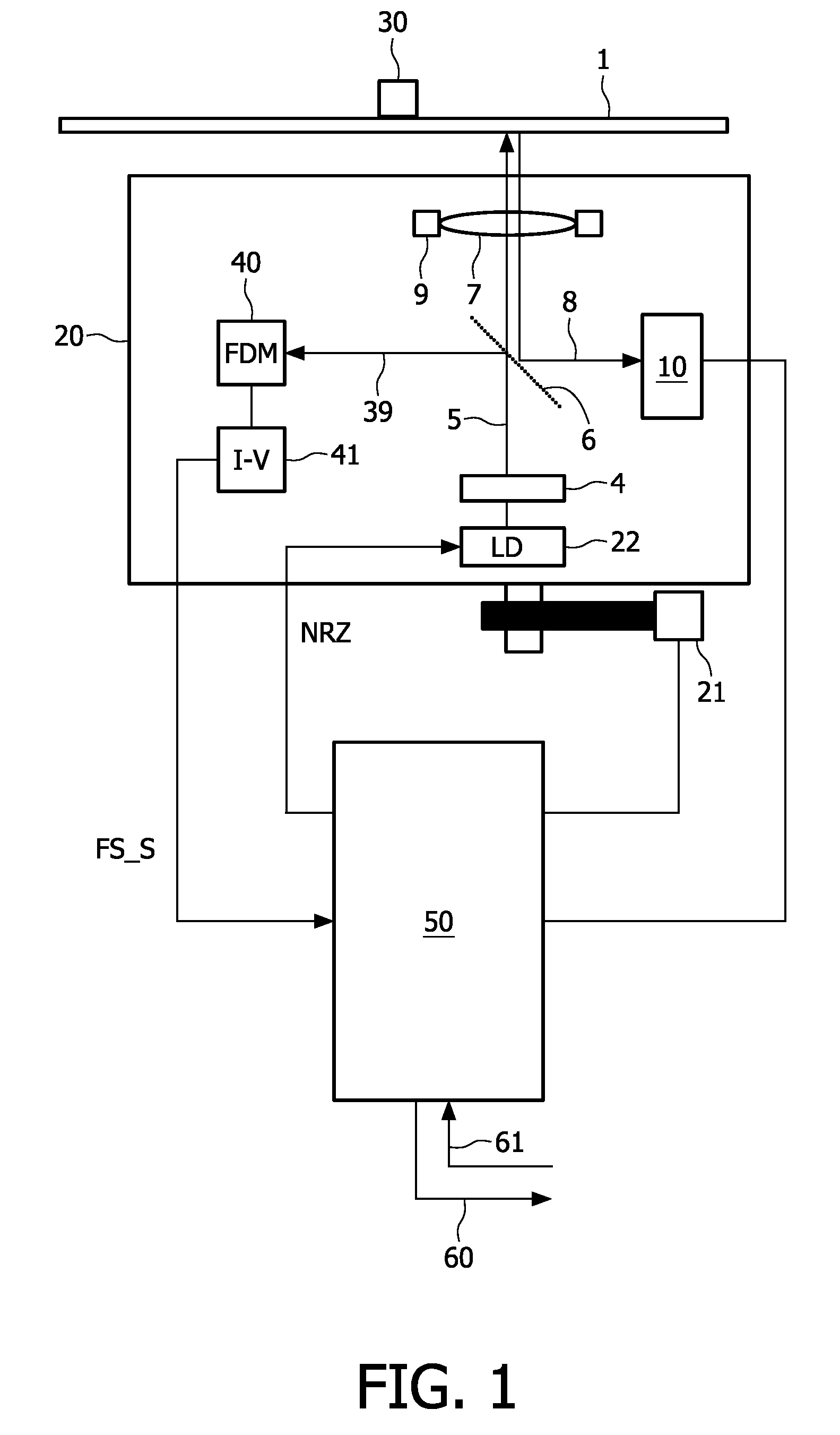
[0048]FIG. 1 shows an optical recording apparatus or an optical drive and an optical carrier 1 according to the invention. The carrier 1 is fixed and rotated by holding means 30.

[0049]The carrier 1 comprises a material suitable for recording information by means of a radiation beam 5. The recording material may, for example, be of the magneto-optical type, the phase-change type, the dye type, metal alloys like Cu / Si or any other suitable material. Information may be recorded in the form of optically detectable regions, also called “marks” for rewriteable media, on the optical carrier 1.

[0050]The apparatus comprises an optical head 20, sometimes called an optical pick-up (OPU), the optical head 20 being displaceable by actuation means 21, e.g. an electric stepping motor. The optical head 20 comprises a photo detection system 10, a laser driver device 30, a radiation source 4, a beam splitter 6, an objective lens 7, and lens displacement means 9 capable of displacing the lens 7 both i...


PUM


Abstract

The invention relates to an optical drive for recording information on an optical carrier or disk (1). The optical drive has a radiation source (4) controllable by control means (50, 22) having calibrated values for a threshold current (I_THR_O) and a change current (I_delta_O). The control means (50, 22) is adapted for: 1) re-calibrating the change current (I_delta_O) using the corresponding threshold current (I_THR_O) to a re-calibrated change current (I_delta—1) by application of a power difference (delta_P), and 2) applying the re-calibrated change current (I_DEL—1) together with the calibrated threshold current (I_THR_O). The re-calibration is performed by refining or re-adapting the change current during operation of the optical drive. It is a distinct advantage of the present invention that the re-calibration of the change current can be performed with no or very little time consumption.

Description

FIELD OF THE INVENTION[0001]The present invention relates to an optical drive or an optical recording apparatus for recording on an associated optical carrier, the optical drive comprising means for re-calibrating a power level of a radiation beam, e.g. a laser beam, used for recording. The invention also relates to corresponding controlling means and a corresponding method.BACKGROUND OF THE INVENTION[0002]During optical recording of an optical disk or carrier, for rewriteable media, a laser beam is applied to selectively crystallize or make amorphous a phase-changing material in dependency of the data to be writing on the optical disk or carrier. Equally, for write-once media, a laser beam is applied to selectively to alter / burn away / deform (dye) material or not, in dependency of the data to be writing on the optical disk or carrier. The laser is driven using a pulse form that contains higher frequency component than the channel rate itself. This has the form of a multi-level pulse...

Claims


Application Information

Patent Timeline
IPC IPC(8): G11B7/12G11B7/125
CPCG11B7/1263H01S5/0683H01S5/0617
Inventor VAN RENS, JEANNETLOOIJKENS, MARIOMCCORMACK, JAMES JOSEPH ANTHONY
Owner KONINKLIJKE PHILIPS ELECTRONICS NV
Learn More