
Conference table assembly

a technology for assembly and tables, applied in the field of conference tables, can solve the problems of affecting the use of the table top for other purposes, affecting the use of the table top, and consuming a lot of time for the transition between presenters,

Active Publication Date: 2009-10-22
STEELCASE INC
View PDF63 Cites 36 Cited by
  • Summary
  • Abstract
  • Description
  • Claims
  • Application Information

AI Technical Summary

Benefits of technology

[0013]It has been recognized that a storage space can be provided below a table top opening for receiving control cables when the cables are not in use or to receive portions of control cables that are not in use. It has also been recognized that a weight of some type can be linked to each of the control cables below the top surface where the weight tends to pull the cable into the space below the table top to aid a cable user in moving the cable back into the space when not in use. Moreover, it has been recognized that the weight can substantially automatically take up any slack in a control cable between a handset that includes a control button and the table top opening so that excess cable is removed from the table top surface.
[0014]The handset can be constructed to be relatively heavy so that the handset can be placed on the table top surface and remain in its disposed position despite the weight tending to pull the handset and cable back into the storage space. Also, to this end, the handset may include rubber or tacky plastic strips or foot members on an undersurface to help maintain the position of the handset after placement on a work surface or the like. Moreover, the handset may include rubber strips or the like on a side or circumferential surface to help retain the handset in a receiving cavity during storage. The handset may, in some cases, include audio and / or video jacks that can be linked to a laptop computer or the like. Here, the handset weight serves the additional purpose of reducing force applied to laptop audio and video jacks. In at least some cases a deck member may be provided in the space below the table top member and on which the handsets can be placed and supported when not in use and door members may be provided to substantially cover (e.g., leave a slot open along one or more edges for cables to pass through) the opening when desired.

Problems solved by technology

Here, transitions between presenters take time and are extremely disruptive.
While a switcher and associated cables enable relatively quick transitions between presenters, these solutions typically require a large number of cables to be strewn across the top surface of a conference table.
To this end, in addition to audio and video cables, power and data cables are often disposed on the top surface of the conference table and the garble of cables is unsightly and impedes use of the table top for other purposes (e.g., laying out of papers, etc.).
Thus, when audio / video / control cables are not being used (e.g., after a conference has been completed), the cables often remain strewn across a table top and the overall scene is unsightly.
First, because the dispenser housing is located on top of the table top, the housing is always observable and reduces the elegance of an associated conference table and space.
Second, where larger diameter cables such as audio and video cables are used, a simple spring loaded dispenser may need to be relatively large and the spring force would have to be relatively high to accomplish the retracting activity and therefore the overall size of the dispensing system would have to be increased appreciably.
Thus, a spring loaded table top mounted dispensing system is not practical for many applications and, at best, solves the data cable management problem in a relatively unsightly manner.
Thus, while solutions for managing power and data cables have been developed, similar solutions have not been developed for audio / video / control cables that form part of a switcher system and that typically remain within a conference space along with a switcher device after a conference has been completed.

Method used


Image

  • Conference table assembly
  • Conference table assembly
  • Conference table assembly

Examples


Embodiment Construction

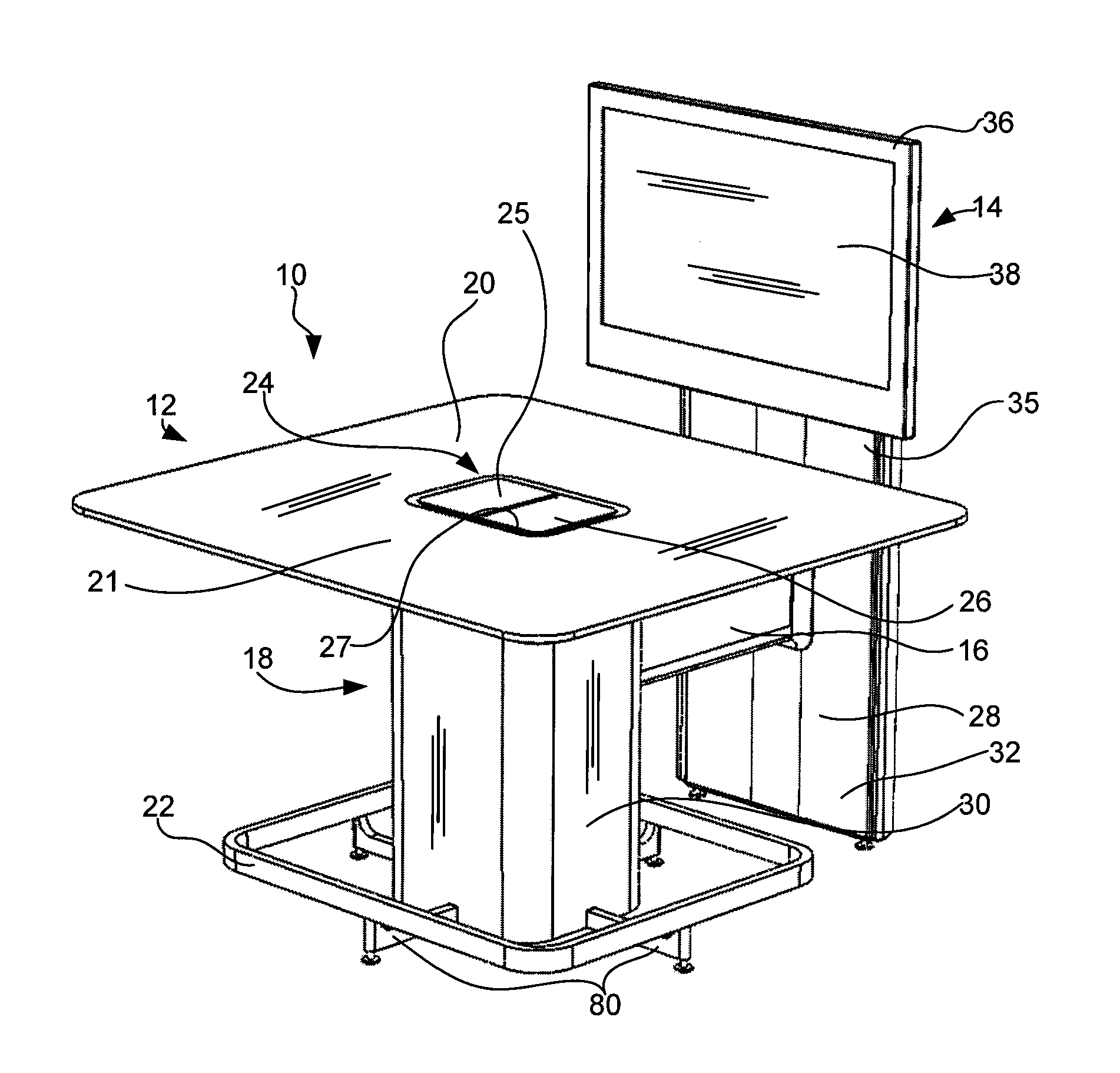
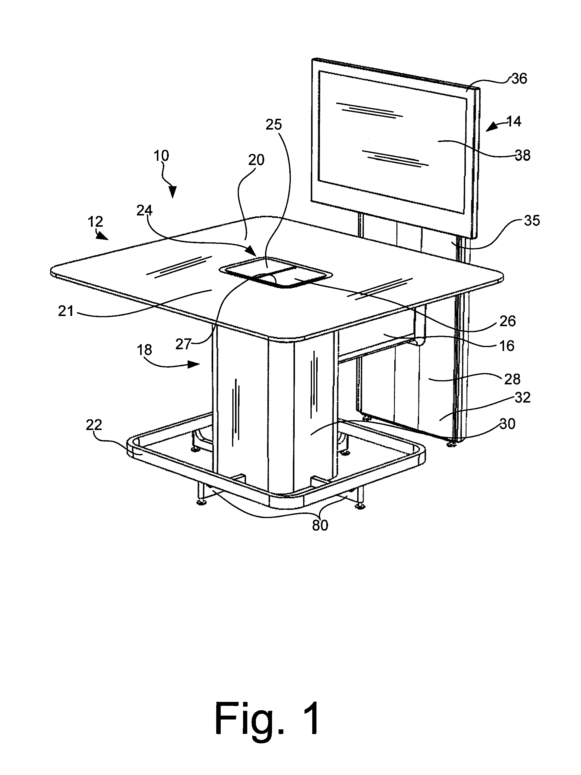
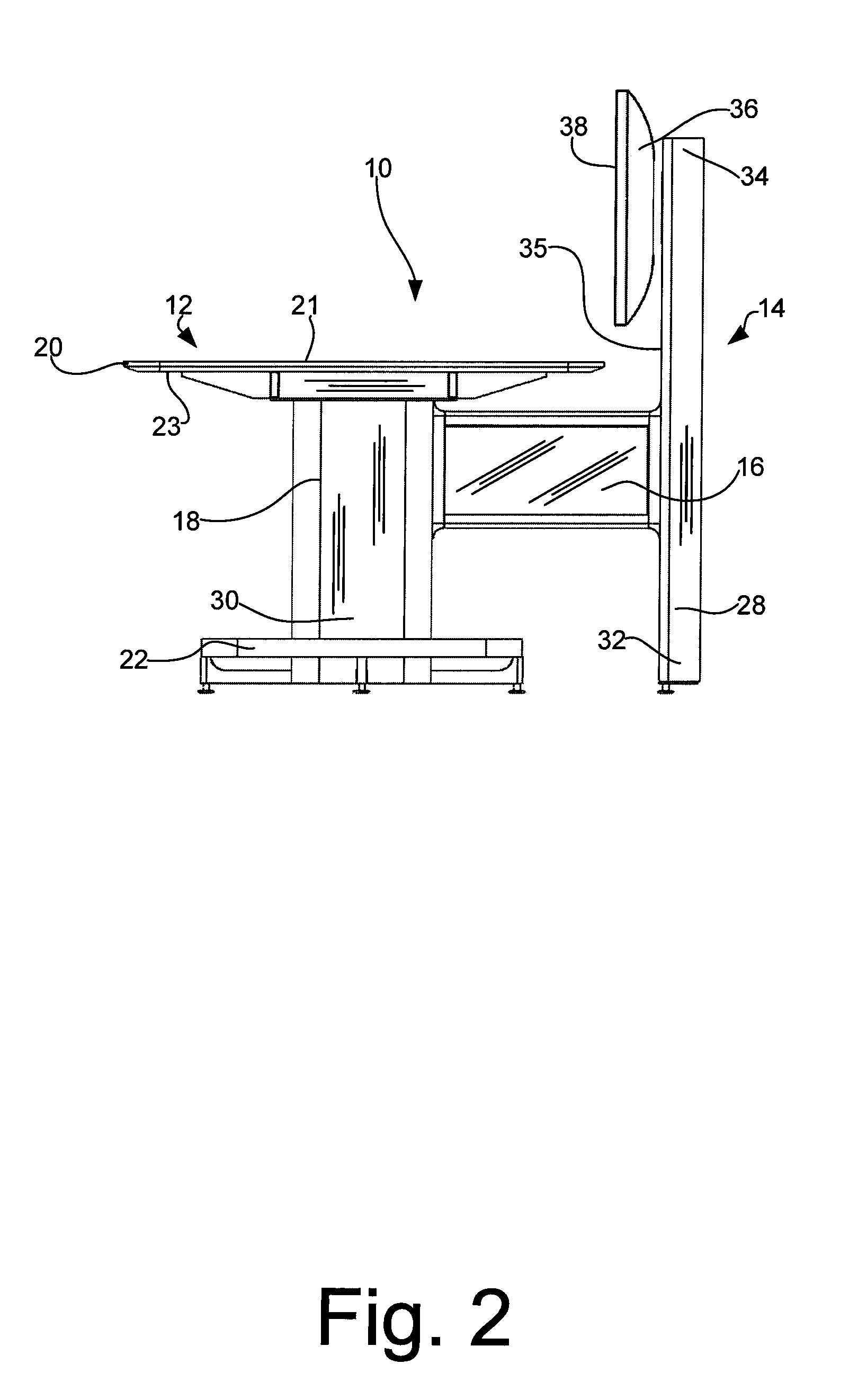
[0056]Referring now to the drawings wherein like reference numerals correspond to similar elements throughout the several views and, more specifically, referring to FIGS. 1-6, the present invention will be described in the context of an exemplary conferencing table configuration or assembly 10 including a table assembly 12, a totem / display assembly 14 and a bridge assembly 16. Table assembly 12 includes a leg support structure 18, a table top member 20 and wire management assembly 24. Referring also to FIGS. 6 and 14, leg support structure 18 includes vertical leg members 76, horizontal foot members 80, a foot rail 22, horizontal shoulder members 77 and a top plate 79. In at least some embodiments, four vertical leg members 76 are provided (only two illustrated) and the leg members are spaced apart to form a rectilinear leg cavity 82. Four foot members 80 extend from the vertical leg members 76 or other leg structural components (e.g., horizontal members that extend between bottom e...


PUM


Abstract

A conferencing assembly for use with at least one computer, the assembly including a table top forming a table top opening, a leg support structure, a display screen supported adjacent the top surface, a switcher for controlling input to the display screen, a plurality of handsets, each hand set including a selector button usable to send a signal to the switcher thereby causing the switcher to link a computer associated with the selector button to the display, a plurality of handset cables, each handset cable having first and second ends linked to the switcher and an associated selector button, respectively, for passing signals from the selector buttons to the switcher, a take up assembly including a separate weight for each of the handset cables, the take up assembly disposed below the top member and aligned with the top opening, each handset cable linked to an associated weight, each weight applying a force tending to pull the second end of the associated handset cable into the opening.

Description

CROSS-REFERENCE TO RELATED APPLICATIONS[0001]This application is based on and claims priority to U.S. Provisional Patent Application Ser. No. 60 / 979,668 filed on Oct. 12, 2007 and entitled “Conference Table Assembly.”STATEMENT REGARDING FEDERALLY SPONSORED RESEARCH OR DEVELOPMENT[0002]Not applicable.BACKGROUND OF THE INVENTION[0003]The present invention relates to conferencing furniture and more specifically to conferencing tables for use with one or more display screens where multiple conference attendees can provide content for driving images presented via the display screen(s).[0004]Small group (e.g., up to 8 attendees) conference tables have been designed that include one or more large display screens adjacent a table top edge or wall mounted or ceiling hung display or projection screens offset a distance from a table top edge. Here, the idea has been to provide information at or near a table edge for attendees to refer to during discussions and presentations. In many cases atte...

Claims


Application Information

Patent Timeline
IPC IPC(8): A47B37/00
CPCA47B37/00H04N5/268H04N7/183A47B13/08A47B21/00A47B21/06A47B83/001A47B2021/066A47B2083/003A47B2083/006G06F1/1632G06F1/1647G06F3/0481G06F3/1423G06F3/1446G06F3/147H04N5/64H04N5/66H04N7/104H04N7/142H04N7/147H04N7/15
Inventor EPSTEIN, LEWIS MARKDOERKSEN, KYLE J.ADAMS, MATTHEW ROBERTCHENG, LARRYMASON, BRIAN JOSEPHOVERTHUN, THOMASPELMAN, TODD ALLENRAO, VIVEK MOHANRINALDIS, DAVID JOHNSCHERRER, LUKAS MARTINSIMINOFF, MARK D.STAGE, SUSANNESTUDENT, JOERG CHRISTOPHLUDWIG, JAMES NOLANKINCALD, BRETT ROBERT
Owner STEELCASE INC
Learn More