
Method and apparatus for the treatment of the intervertebral disc annulus

Inactive Publication Date: 2009-10-15
KRT INVESTORS
View PDF11 Cites 109 Cited by
  • Summary
  • Abstract
  • Description
  • Claims
  • Application Information

AI Technical Summary

Benefits of technology

[0012]The present inventions provide methods and related devices for reconstruction of the disc wall in cases of displaced, herniated, thinned, ruptured, or otherwise damaged or infirm intervertebral discs. In accordance with the invention, a method is disclosed for intervertebral disc reconstruction for treating a disc having an aperture, weakened or thin portion in the wall of the annulus fibrosis of the intervertebral disc. Repair, reconstruction, sealing, occluding an aperture, weakened or thin portion in the wall of the annulus may prevent or avoid migration of intradiscal material from the subannular space.
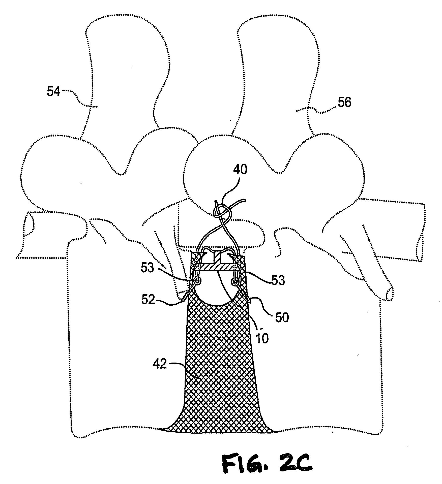
[0013]The method of the invention includes, in one aspect, a method of intervertebral disc repair for treating a disc having a defect in the wall of the disc's annulus fibrosus In this regard, the method comprises providing a bone anchor having a shortenable elongate member attached thereto, inserting the bone anchor into a vertebra that is contiguous to a disc having a defect in the wall of the disc's annulus fibrosus, and disposing a portion of the elongate member proximate to the defect in the wall of the annulus fibrosus. The method further comprises providing a fixation device having a first member, a second member, and a connecting element therebetween, placing the first member of the fixation device into, or through, the wall of the annulus fibrosus on a first side of the portion of the elongate member, placing the second member of the fixation device into, or through, the wall of the annulus fibrosus on a second side of the portion of the elongate member so that the connecting element between the first member and the second member extends across the portion of the elongate member, and shortening the elongate member to an extent sufficient to cause the connecting element between the first member and the second member to be drawn in tension to pull, wholly or partially, annulus fibrosus tissue toward the bone anchor in the vertebra.
[0014]In another aspect, the disclosed invention is a method for repair of a defect in the annulus fibrosus tissue of an intervertebral disc. In this regard, the method comprises inserting a bone anchor having a shortenable elongate member attached thereto into a vertebra that is contiguous to a disc having a defect to be repaired in the disc's annulus fibrosus tissue, aligning a portion of the elongate member proximate to the defect, inserting a first anchor member having a first elongate element attached thereto into or through annulus fibrosus tissue on one side of the portion of the elongate member, and inserting a second anchor member having a second elongate element attached thereto into or through the annulus fibrosus tissue on the other side of the portion of the elongate member. The method further comprises providing an adjustable coupling that extends over the portion of the elongate member between the first elongate element of the first anchor member and the second elongate element of the second anchor member, applying tension to the coupling between the first and second elongate elements, and shortening a length of the elongate member between the bone anchor and the coupling.

Problems solved by technology

Without a competent disc, collapse of the intervertebral disc may occur, contributing to abnormal joint mechanics and premature development of degenerative and / or arthritic changes.
Similarly, the nucleus desiccates, increasing viscosity and thus losing its fluidity.
In combination, these features of the aged intervertebral discs result in less dynamic stress distribution because of the more viscous nucleus pulposus, and less ability to withstand localized stresses by the annulus fibrosus due to its desiccation, loss of flexibility and the presence of fissures.
Additionally, injury, disease or other degenerative disorders may cause one or more of the intervertebral discs to shrink, collapse, deteriorate or become displaced, herniated, or otherwise damaged and compromised.
Historically, there has been no known way to repair or reconstruct the annulus.
While results are currently acceptable, they are not optimal.

Method used


Image

  • Method and apparatus for the treatment of the intervertebral disc annulus
  • Method and apparatus for the treatment of the intervertebral disc annulus
  • Method and apparatus for the treatment of the intervertebral disc annulus

Examples


Embodiment Construction

[0084]Reference will now be made in detail to selected illustrative embodiments of the invention, with occasional reference to the accompanying drawings. Wherever possible, the same reference numbers will be used throughout the drawings to refer to the same or like parts.

[0085]In the surgical repair of an aperture in the annulus, as shown in FIG. 1 and as described in related commonly-assigned U.S. Pat. No. 6,592,625 to Cauthen, a damaged annulus 42 is repaired by use of surgical sutures 40. One or more surgical sutures 40 are placed at about equal distances along the sides of a pathologic aperture 44 in the annulus 42. Reapproximation or closure of the aperture 44 is accomplished by tying the sutures 40 so that the sides of the aperture 44 are drawn together. The reapproximation or closure of the aperture 44 enhances the natural healing and subsequent reconstruction by the natural tissue (e.g., fibroblasts) crossing the now surgically narrowed gap in the annulus 42. Preferably, the...


PUM

PropertyMeasurementUnit
Lengthaaaaaaaaaa
Structureaaaaaaaaaa
Tensionaaaaaaaaaa

Abstract

This disclosure presents methods and devices for treating a tear, rent, incision, defect, aperture or delamination of the annulus fibrosus of an intervertebral disc. The methods and devices can employ fixation delivery apparatuses, fixation apparatuses, patch delivery tools and patches positioned, at least in part, in or on aspects of an intervertebral disc for treatment of the intervertebral disc or its components. In some aspects, these techniques include the use of this includes a fixation apparatus that includes at least one bone anchor connected to at least one disc anchor by a shortenable elongate member.

Description

CROSS-REFERENCE TO A RELATED APPLICATIONS[0001]This application is a continuation-in-part of application Ser. No. 11 / 686,599, filed on May 15, 2007; which is a continuation of application Ser. No. 11 / 120,750, filed on May 3, 2005; which is a continuation-in-part of U.S. patent application Ser. No. 10 / 352,981 filed Jan. 29, 2003 and a continuation-in-part of U.S. patent application Ser. No. 10 / 327,106 filed Dec. 24, 2002, each of which are continuations-in-part of U.S. patent application Ser. No. 10 / 133,339 filed Apr. 29, 2002, which is a continuation-in-part of U.S. patent application Ser. No. 09 / 947,078, filed Sep. 5, 2001, now U.S. Pat. No. 6,592,695, issued Jul. 15, 2003, which is a continuation of U.S. patent application Ser. No. 09 / 484,706, filed Jan. 18, 2000, which claims the benefit of U.S. Provisional Application No. 60 / 160,710, filed Oct. 20, 1999. This application also claims, through application Ser. No. 10 / 133,339 the benefit of U.S. Provisional Application No. 60 / 309,1...

Claims


Application Information

Patent Timeline
IPC IPC(8): A61B17/84A61B17/04
CPCA61B17/0057A61F2310/00155A61B17/0469A61B17/0487A61B17/064A61B2017/0065A61B2017/00659A61B2017/00663A61B2017/0414A61B2017/0417A61B2017/044A61B2017/0462A61B2017/0472A61B2017/0474A61B2017/0475A61B2017/0477A61B2017/0496A61B2017/06052A61B2017/0646A61B2017/0647A61B2019/306A61F2/0063A61F2/30907A61F2/442A61F2/4611A61F2002/2817A61F2002/30062A61F2002/3008A61F2002/30093A61F2002/30158A61F2002/30299A61F2002/30448A61F2002/30451A61F2002/30462A61F2002/30777A61F2002/30784A61F2002/30841A61F2002/4435A61F2002/444A61F2002/4623A61F2002/4627A61F2002/4662A61F2210/0004A61F2210/0019A61F2220/005A61F2220/0058A61F2220/0075A61F2230/0026A61F2230/0093A61F2250/0098A61F2310/00017A61F2310/00023A61F2310/00029A61B17/0401A61F2/4603A61F2002/30092A61B2090/036
Inventor BENTLEY, ISHMAELBURNS, MATTHEW M.CAUTHEN, III, JOSEPH C.DUKART, BRIAN L.HOUFBURG, RODNEY L.WALES, LAWRENCE W.WESSMAN, BRADLEY J.
Owner KRT INVESTORS
Learn More