
Chain tensioner device

a tensioner device and chain technology, applied in the direction of belts/chains/gearrings, mechanical equipment, belts/chains/gears, etc., can solve the problems of reducing the stroke of the plunger more than necessary, reducing and undesirable reducing the stroke of the plunger. , to achieve the effect of reducing the stroke of the plunger and increasing the extension and contraction response of the plunger

Active Publication Date: 2009-10-15
HONDA MOTOR CO LTD
View PDF9 Cites 7 Cited by
  • Summary
  • Abstract
  • Description
  • Claims
  • Application Information

AI Technical Summary

Benefits of technology

[0007]The present invention is achieved in view of the above described circumstances, and an aspect of the invention is to ensure a stroke of a tensioner arm of a chain tensioner device and reduce a stroke of a plunger of a tensioner lifter to increase the extension and contraction response of the plunger.
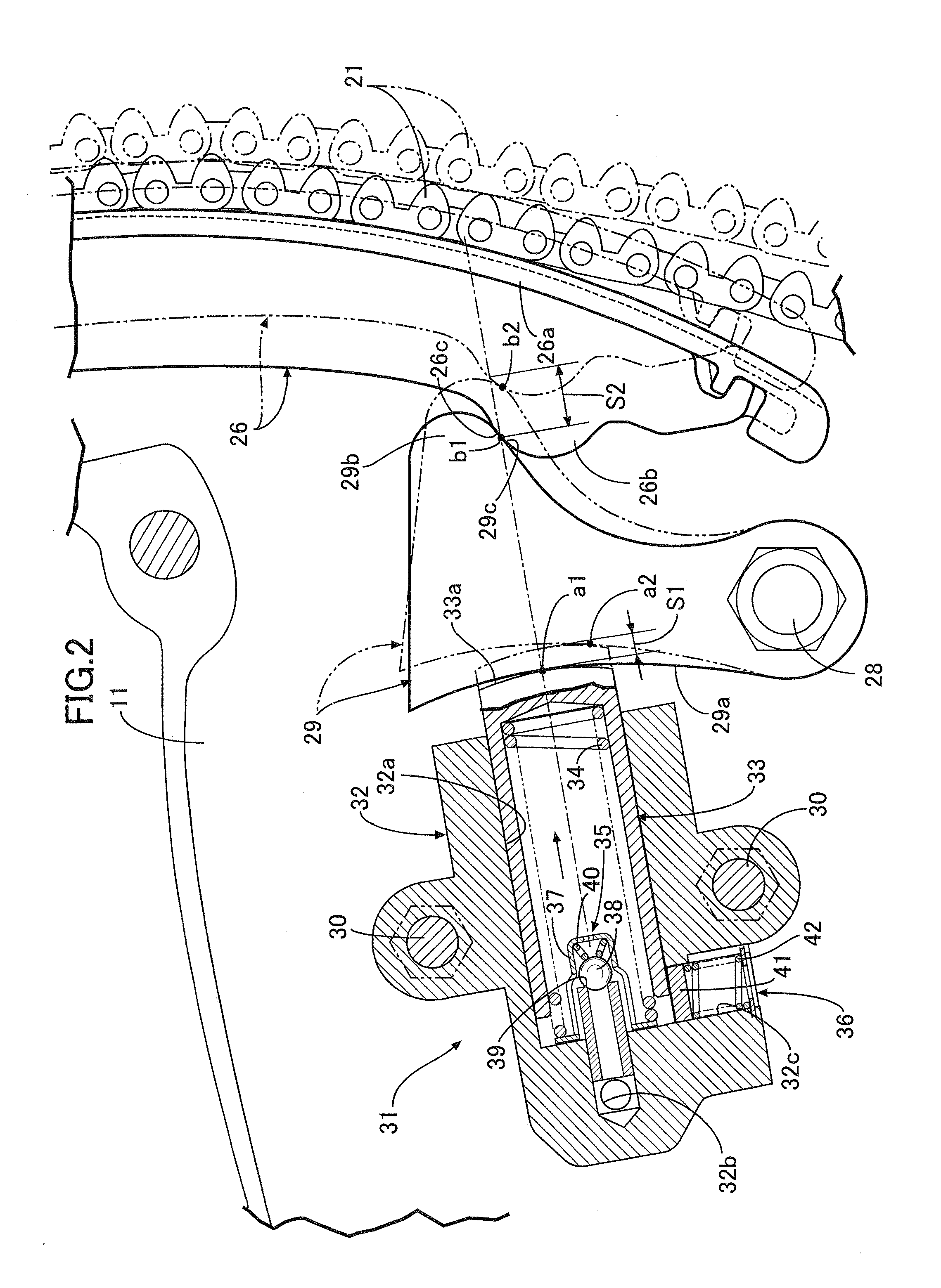
[0009]With the above described structural configuration, the first slide surface of the main arm that is pivotably supported by the first support shaft, and the second slide surface of the sub-arm that is pivotably supported by the second support shaft slidably abut against each other. As such, when the main arm is biased by the biasing force of the tensioner lifter via the sub-arm toward the endless chain, the stroke of the tensioner lifter is enhanced or increased and transferred to the main arm. Thus, even with relatively large or substantial changes in the tension of the endless chain, the tensioner lifter can merely generate a small stroke that causes the main arm to follow the endless chain with high response to provide or maintain stable tension of the endless chain, thereby increasing the power transmission performance and durability of the tensioner lifter.
[0011]With the above described structural configuration, the stroke of the tensioner lifter is enhanced or increased and transferred to the main arm by using a relatively simple structural arrangement.
[0013]With the above described structural configuration, a load applied from the endless chain to the main arm is transferred from the sub-arm to the tensioner lifter without being increased, thereby reducing the load applied to the tensioner lifter and reducing the size of the tensioner lifter.
[0015]With the above described structural configuration, an edge of the tip end portion of the plunger is prevented from contacting the back surface of the sub-arm, and ensures a sufficient pivot angle of the sub-arm with respect to the stroke of the plunger.

Problems solved by technology

Thus, there is a problem wherein an increase in the plunger stroke reduces extension and contraction response, and wherein the extension and contraction of the plunger cannot follow or correspond to changes in the tension of the timing chain during short intervals.
To increase the extension and contraction response of the plunger, the stroke of the plunger needs to be reduced, but reducing the stroke of the plunger more than necessary is undesirable for ensuring a required stroke of the tensioner arm.

Method used


Image

  • Chain tensioner device
  • Chain tensioner device
  • Chain tensioner device

Examples


first embodiment

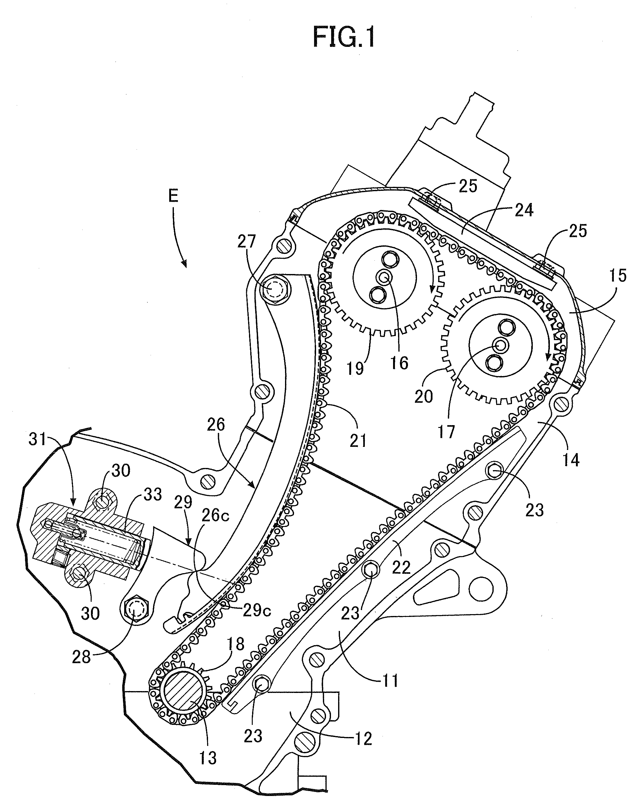
[0023]the present invention will be explained below in conjunction with FIGS. 1 to 3B.

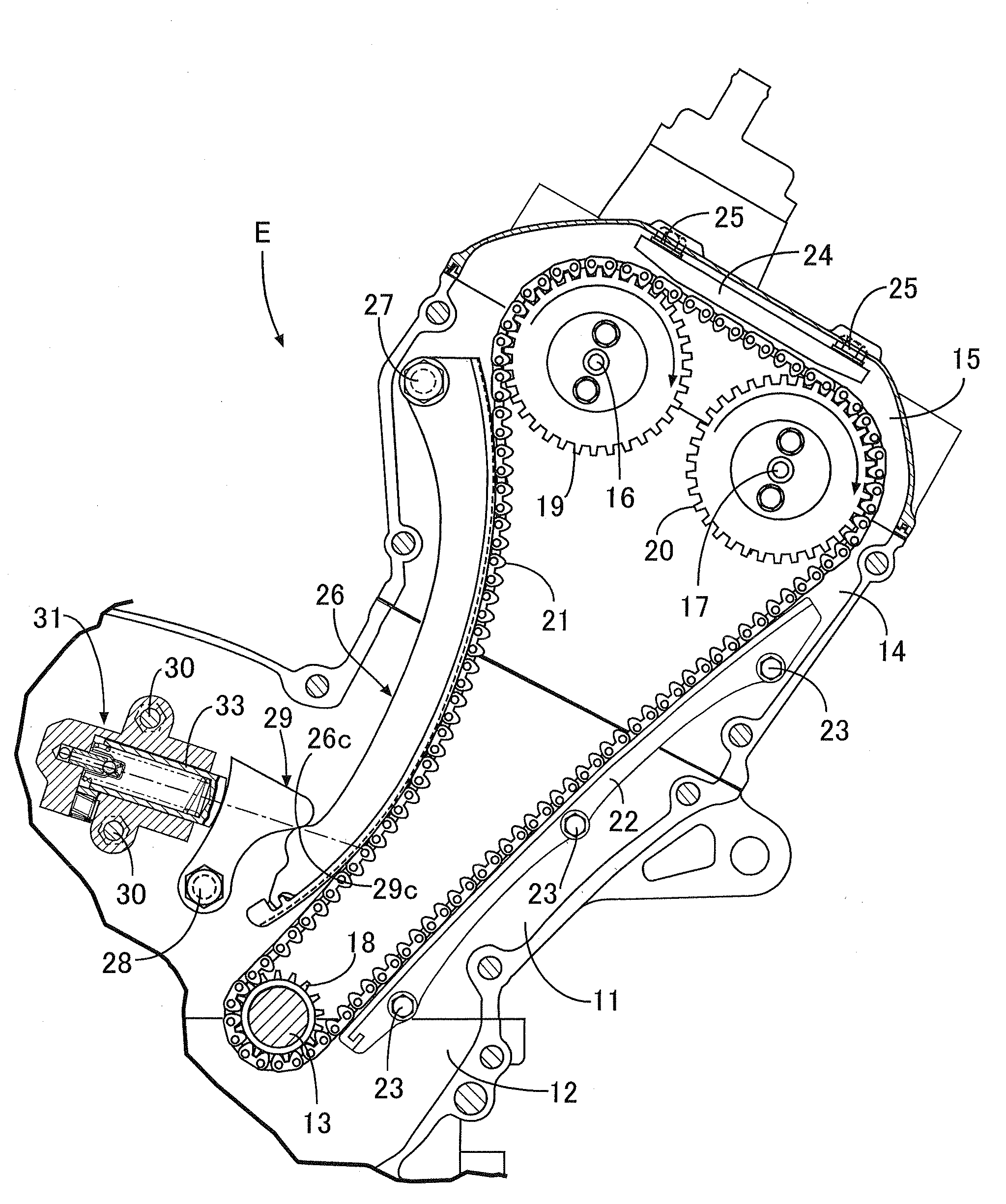
[0024]As shown in FIG. 1, a crankshaft 13 is rotatably supported between a cylinder block 11 of an engine E and a crankcase 12 connected to a lower surface of the cylinder block 11. An intake camshaft 16 and an exhaust camshaft 17 are rotatably supported between a cylinder head 14 connected to an upper surface of the cylinder block 11 and a head cover 15 connected to an upper surface of the cylinder head 14. A timing chain 21 formed by an endless chain is wrapped around a drive sprocket 18 and two follower sprockets 19 and 20. The drive sprocket 18 is provided on an end of the crankshaft 13 and the follower sprockets 19 and 20 are provided on ends of the intake camshaft 16 and the exhaust camshaft 17, respectively. The intake camshaft 16 and the exhaust camshaft 17 are driven at a rotational speed that is half of the rotational speed of the crankshaft 13.

[0025]A first fixed chain guide 22 brought i...

second embodiment

[0043]Next, the present invention will be explained in conjunction with FIG. 4.

[0044]The second embodiment differs from the first embodiment in that the second support shaft 28 is provided at an upper end of a sub-arm 29, instead of at the lower end of the sub-arm 29 as in the first embodiment. A first slide surface 26c provided on a lower side of a bump 26b of a main arm 26 slidably abuts against a second slide surface 29c provided on an upper side of a bump 29b of the sub-arm 29. As in the first embodiment, the first slide surface 26c of the main arm 26 abuts against the second slide surface 29c of the sub-arm 29 on the side of the second support shaft 28 of the sub-arm 29.

[0045]Also, the stroke of a lower end of the main arm 26 can be larger than the stroke of the plunger 33 to obtain the same operation and effect as in the first embodiment.

third embodiment

[0046]Next, the present invention will be explained in conjunction with FIG. 5.

[0047]In the first and second embodiments, the tensioner lifter 31 is positioned so as to significantly or greatly cross a cylinder axis, while in the third embodiment, the tensioner lifter 31 is positioned to be substantially in parallel with the cylinder axis. The sub-arm 29 is L-shaped and has a bent portion pivoted on the cylinder block 11 by a second support shaft 28, an abutment portion 29d at a tip end of a short side abuts against a tip end portion 33a of the plunger 33, and a second slide surface 29c at a tip end of a long side abuts against a first slide surface 26c at a lower end of a main arm 26. The short side of the sub-arm 29 is positioned to substantially be orthogonal relative to the cylinder axis, and the long side of the sub-arm 29 is positioned to substantially be in parallel with the cylinder axis.

[0048]A length b of the long side is preferably twice or more a length a of the short si...


PUM


Abstract

A chain tensioner device having a first slide surface of a main arm pivotably supported at an upper end thereof, and a second slide surface of a sub-arm pivotably supported at a lower end thereof. The first and second slide surfaces slidably abut against each other. When the main arm is biased toward a timing chain via the sub-arm by a biasing force of a plunger of a tensioner lifter, a stroke of the main arm is increased with respect to a stroke of the plunger.

Description

CROSS-REFERENCE TO RELATED APPLICATIONS[0001]This application is based upon and claims the benefit of priority from the prior Japanese Patent Application Nos. 2008-104406 and 2009-011669, filed Apr. 14, 2008 and Jan. 22, 2009, respectively, the entire contents of which are incorporated herein by reference.BACKGROUND OF THE INVENTION[0002]1. Field of the Invention[0003]The present invention relates to a chain tensioner device having a main arm pivotably supported by a first support shaft and brought into slide contact with an endless chain to apply a predetermined tension to the endless chain. The endless chain is wrapped around a drive sprocket provided on a driving shaft and a follower sprocket provided on a follower shaft. A tensioner lifter generates a biasing force to bias the main arm toward the endless chain. A sub-arm is pivotably supported by a second support shaft and transfers the biasing force of the tensioner lifter to the main arm.[0004]2. Description of the Related Art...

Claims


Application Information

Patent Timeline
Patent Type & Authority Applications(United States)
IPC IPC(8): F16H7/08
CPCF16H7/0848F16H2007/0806F16H2007/0872F16H2007/0859F16H2007/0812
Inventor MUGURUMA, NAOKOYAMADA, SHINJIMATSUMOCHI, YUJIFUJIMOTO, YUUJIKOIWA, YOJIRO
Owner HONDA MOTOR CO LTD
Learn More