
Acoustic wide area air surveillance system

a wide-area air and surveillance system technology, applied in the field of surveillance systems, can solve the problems of providing unwanted alertment, limited coverage, and surveillance systems that are often unreliable for tracking low-flying aircraft and tracking aircra

Active Publication Date: 2009-10-15
THE BOEING CO
View PDF4 Cites 106 Cited by
  • Summary
  • Abstract
  • Description
  • Claims
  • Application Information

AI Technical Summary

Problems solved by technology

While these systems may provide coverage in some areas, in other areas coverage is limited by high terrain or distance from widely spaced radar and transponder facilities.
As a result, those surveillance systems are often unreliable for tracking low flying aircraft and for tracking aircraft attempting to evade detection by operating at low altitudes and / or covertly.
In addition, monostatic radar may provide unwanted alertment to the aircraft being tracked.
One solution may be to employ numerous radar systems to cover low altitude areas of interest; however, this approach may be expensive and impractical in many areas.

Method used


Image

  • Acoustic wide area air surveillance system
  • Acoustic wide area air surveillance system
  • Acoustic wide area air surveillance system

Examples


Embodiment Construction

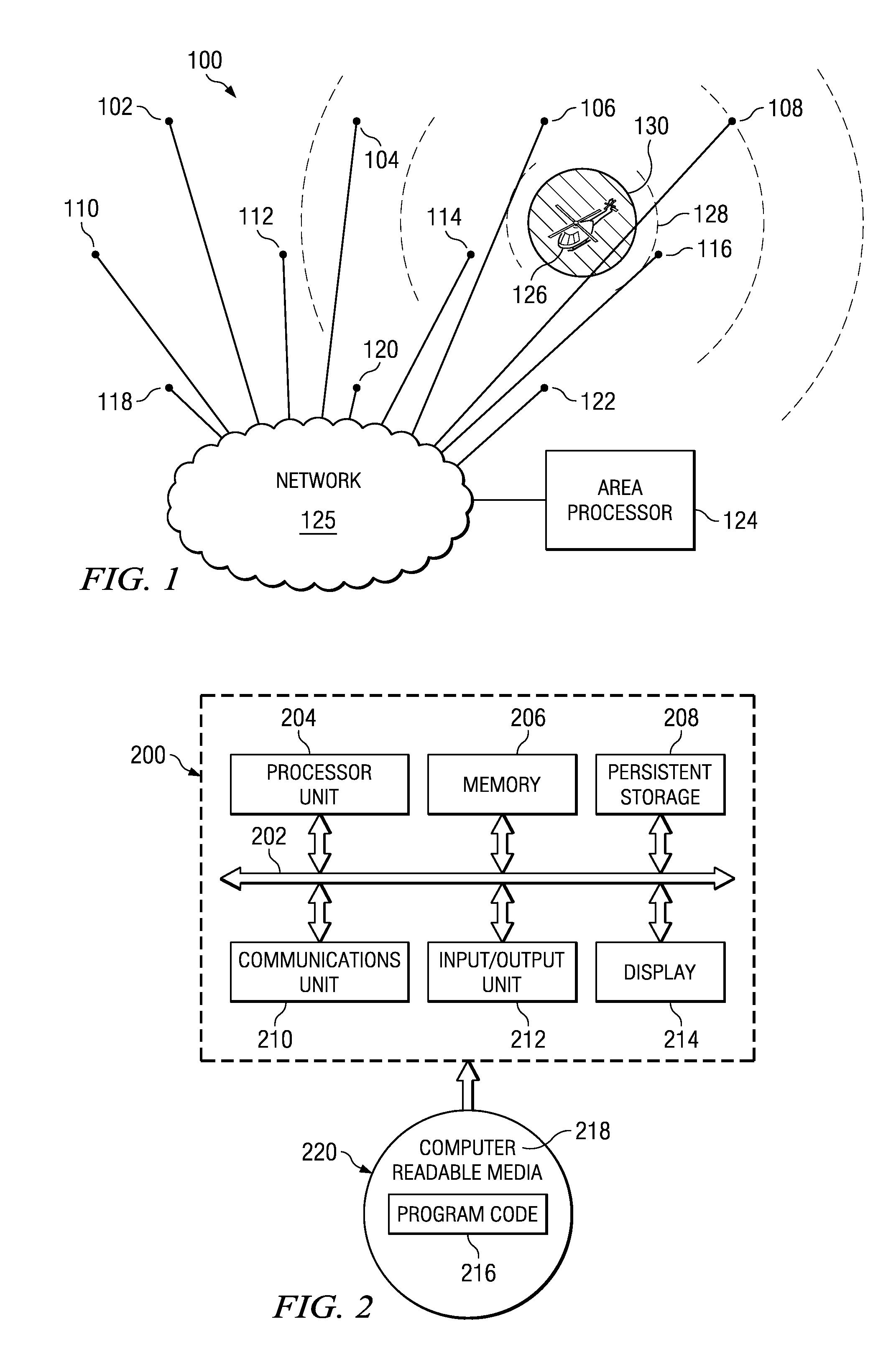
[0025]With reference now to the figures and in particular with reference to FIG. 1, an illustration of an acoustic air surveillance system is depicted in accordance with an advantageous embodiment. In this example, acoustic air surveillance system 100 includes sound sensors 102, 104, 106, 108, 110, 112, 114, 116, 118, 120, and 122. Additionally, acoustic air surveillance system 100 also includes area processor 124 that collects and processes the data from the sensors.

[0026]These sensors may be, for example, acoustic sensors. One or more of these sound sensors may detect acoustic emission 128 generated by aircraft 126. Acoustic emission 128 is the sound that aircraft 126 generates. From acoustic emission 128, a signature may be identified. Aircraft 126 may generate frequencies within acoustic emission 128 that allow for the identification of aircraft 126. In these examples, acoustic emission 128 is the sound that aircraft 126 generates in flight.

[0027]Acoustic air surveillance system...


PUM


Abstract

A method and apparatus for detecting an aircraft. The method is provided for wide area tracking of aircraft. An acoustic emission of the aircraft is detected from a plurality of locations. A position of the aircraft at a set of times is estimated by comparing a set of harmonically related Doppler shifted frequencies for the acoustic emission to an expected zero Doppler shifted frequency of the aircraft to form an estimated position. The position of the aircraft and a heading of the aircraft are tracked using the estimated position. The aircraft type is classified based on the corresponding set of zero Doppler frequencies at each acoustic sensor.

Description

BACKGROUND INFORMATION[0001]1. Field[0002]The present disclosure relates generally to monitoring systems and in particular to a method and apparatus for surveillance for low flying aircraft. Still more particularly, the present disclosure relates to a method and apparatus for detecting, tracking and classifying aircraft using sound sensors distributed over a wide surface area beneath the surveillance area.[0003]2. Background[0004]An ability to detect and locate low flying aircraft is an important capability for areas where surveillance radars do not exist or are hindered by terrain.[0005]Today air traffic control radar and transponder systems, as well as other radar systems, are used to attempt to track and identify aircraft covertly crossing international borders. While these systems may provide coverage in some areas, in other areas coverage is limited by high terrain or distance from widely spaced radar and transponder facilities. As a result, those surveillance systems are often...

Claims


Application Information

Patent Timeline
Patent Type & Authority Applications(United States)
IPC IPC(8): G01S3/80G01C21/00
CPCG01S15/66G01S5/18G01S3/8022G01S3/808G01S5/22G01S11/14
Inventor DAVIS, HENRY H.BALMFORTH, KEVIN DALENIELSEN, RICHARD OVE
Owner THE BOEING CO
Learn More