
Method and apparatus for detecting decrease in tire air pressure and program for determining decrease in tire air pressure

Inactive Publication Date: 2009-10-15
SUMITOMO RUBBER IND LTD
View PDF5 Cites 6 Cited by
  • Summary
  • Abstract
  • Description
  • Claims
  • Application Information

AI Technical Summary

Benefits of technology

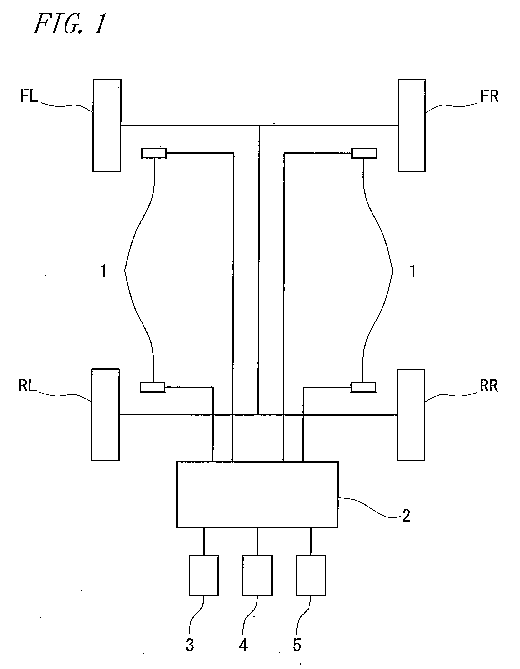
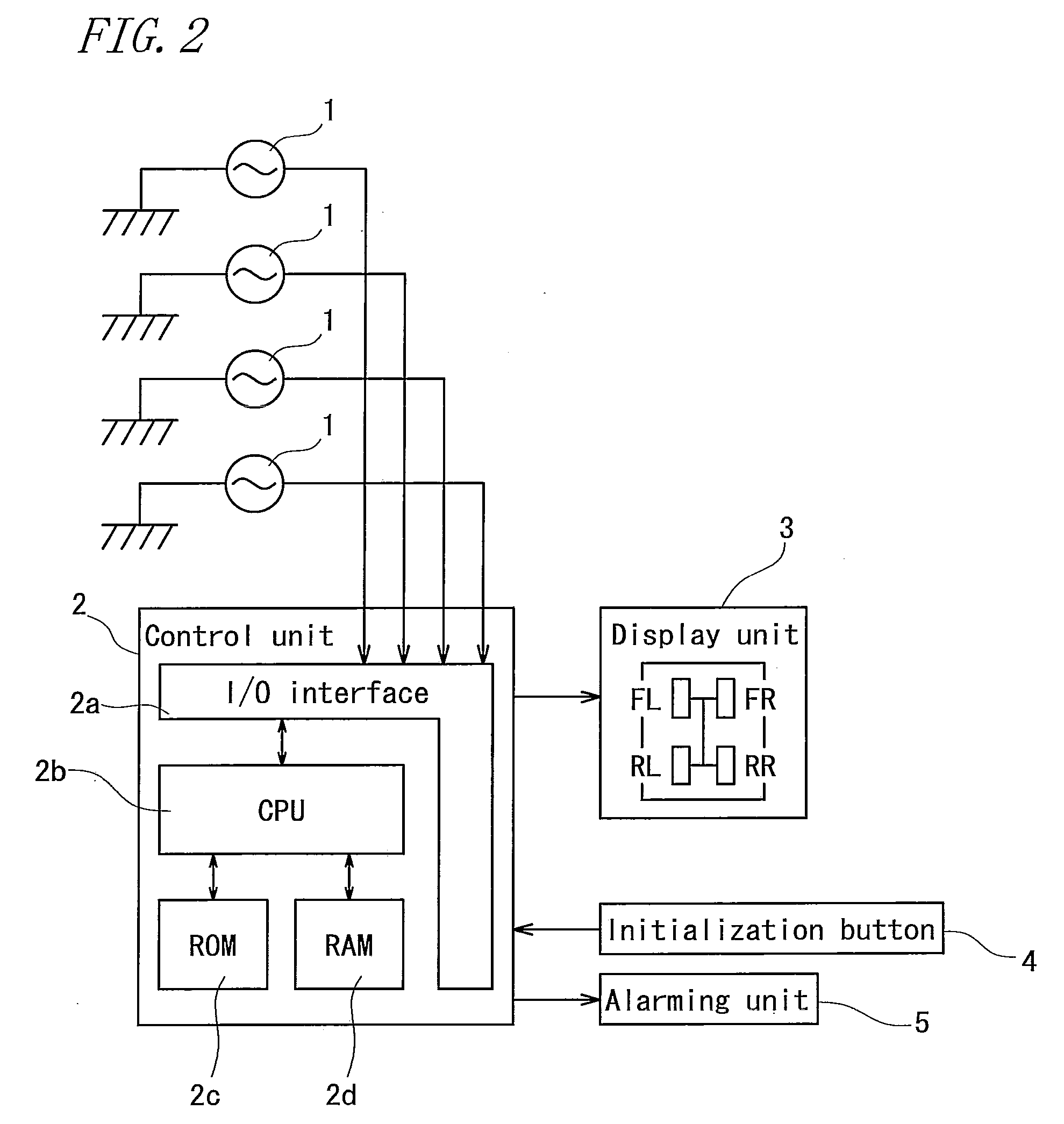
[0029]The apparatus for detecting a decrease in a tire air pressure of the present invention focuses on the following point. In a vehicle for which the distribution of the front and rear driving torque is variable, DEL2 (a decreased pressure judgment value showing a wheel speed ratio between the front and rear axes) depends not on the total values of the driving torque but on a difference between the front and rear driving torque. Thus, the initialization means obtains the second relation formula showing the correlation between a difference in the driving torque and the decreased pressure judgment value. During the vehicle running, whether the distribution of the front and rear driving torque is equidistribution or not is determined. When the distribution of the front and rear driving torque is determined not to be equidistribution, the reference value obtained based on the second relation formula is compared with the decreased pressure judgment value to judge a decrease in a tire air pressure. When the distribution of the front and rear driving torque is determined to be equidistribution on the other hand, a reference value obtained based on the first relation formula showing the correlation between the total of the driving torque calculated by the initialization means and the decreased pressure judgment value is compared with the decreased pressure judgment value to judge a decrease in a tire air pressure. In this manner, in both of the case where the distribution of the front and rear driving torque is equidistribution and the case where the distribution of the front and rear driving torque is not equidistribution, DEL2 can be momentarily monitored to accurately determine whether a regular internal pressure is maintained or not.

Problems solved by technology

In this case, the DEL, which is calculated based on a relative difference in the wheel speed, cannot exclude the influence by the slip rate, consequently causing a wrong judgment of a decreased pressure in spite of a normal pressure.
Thus, it is difficult to use this value of DEL2 to accurately distinguish a decreased pressure status from a regular internal pressure status.

Method used


Image

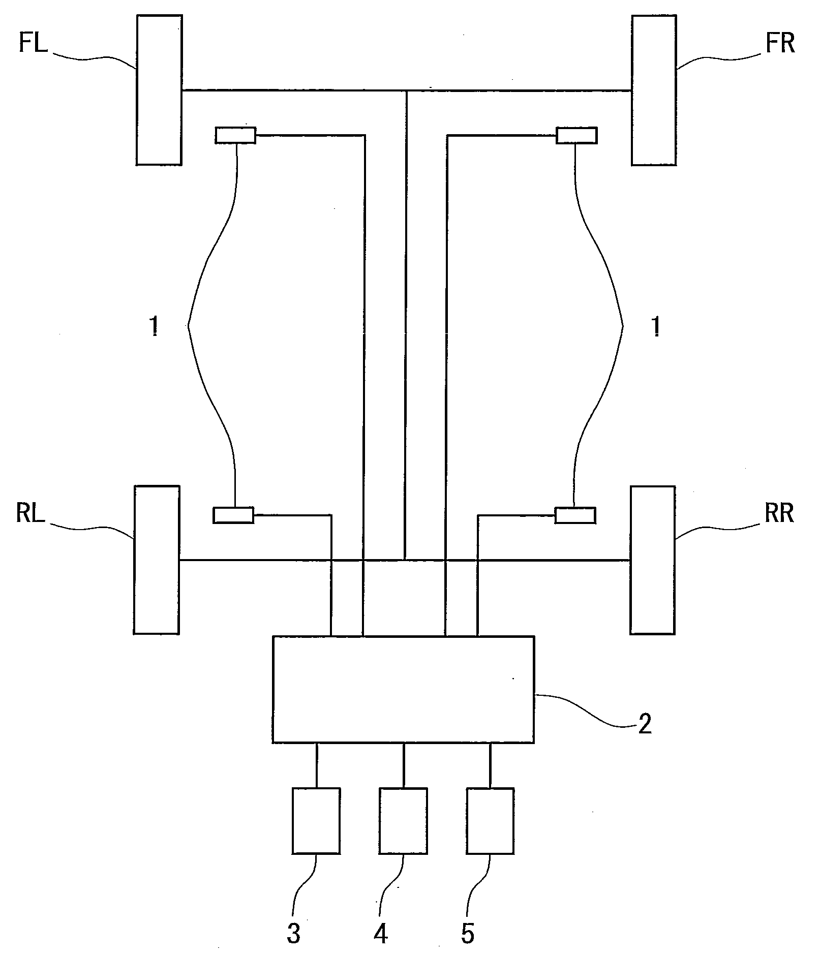
  • Method and apparatus for detecting decrease in tire air pressure and program for determining decrease in tire air pressure
  • Method and apparatus for detecting decrease in tire air pressure and program for determining decrease in tire air pressure
  • Method and apparatus for detecting decrease in tire air pressure and program for determining decrease in tire air pressure

Examples


embodiment

[0056]Tires (225 / 50 R17) were attached to a four-wheel driving vehicle for which the distribution of the front and rear driving torque was variable and the vehicle was subjected to an actual vehicle test at Okayama test course of Sumitomo Rubber Industries. Ltd.

[0057]Initialization was performed with various distributions of the front and rear driving torque at the regular internal pressures (front wheel: 220 kPa, rear wheel: 270 kPa) to obtain the relation of DEL2 to a difference between the front and rear driving torque. The result is shown in FIG. 3. In FIG. 3, the horizontal axis represents a difference between the front and rear driving torque (rear driving torque−front driving torque) and the vertical axis represents DEL2.

[0058]As can be seen from FIG. 3, assuming that the front driving torque is Tfront(t) and the rear driving torque is Trear(t) at a certain time t, the relation of DEL2(t)=−0.016×{Trear(t)−Tfront(t)}+0.02 can be satisfied.

[0059]Next, the vehicle was subjected ...


PUM


Abstract

The method includes: a step of calculating wheel rotation information; a judgment step of judging a decrease in a tire air pressure by comparing a predetermined reference value with a decreased pressure judgment value showing a wheel speed ratio of the front and rear axes; an initialization step of storing the wheel speed ratio between the front and rear axes at the regular internal pressure; and a step of determining whether the distribution of the front and rear driving torque is equidistribution or not.

Description

BACKGROUND OF THE INVENTION[0001]1. Field of the Invention[0002]The present invention relates to a method and an apparatus for detecting a decrease in a tire air pressure and a program for determining a decrease in a tire air pressure.[0003]2. Description of the Related Art[0004]Conventionally, an apparatus for detecting a decrease in a tire air pressure uses a principle according to which a tire having a decreased pressure shows a reduced outer diameter (tire dynamic loaded radius) compared to that of tires having a normal air pressure and thus shows an increased angular velocity (wheel speed) compared to that of other normal tires. In the case of a method of detecting a decrease in an air pressure based on a relative difference in a tire wheel speed for example, a judgment value DEL obtained by DEL={(V1+V4) / 2−(V2+V3) / 2} / {(V1+V2+V3+V4) / 4}×100(%) is used. When an absolute value of this DEL exceeds an alarming threshold value, an alarm is raised (see Japanese Unexamined Patent Public...

Claims


Application Information

Patent Timeline
IPC IPC(8): B60C23/00
CPCB60C23/061
Inventor MIYAMOTO, KAZUYOSHIYANASE, MINAO
Owner SUMITOMO RUBBER IND LTD
Learn More