Ion trap, mass spectrometer, and ion mobility analyzer
- Summary
- Abstract
- Description
- Claims
- Application Information
AI Technical Summary
Benefits of technology
Problems solved by technology
Method used
Image
Examples
first embodiment
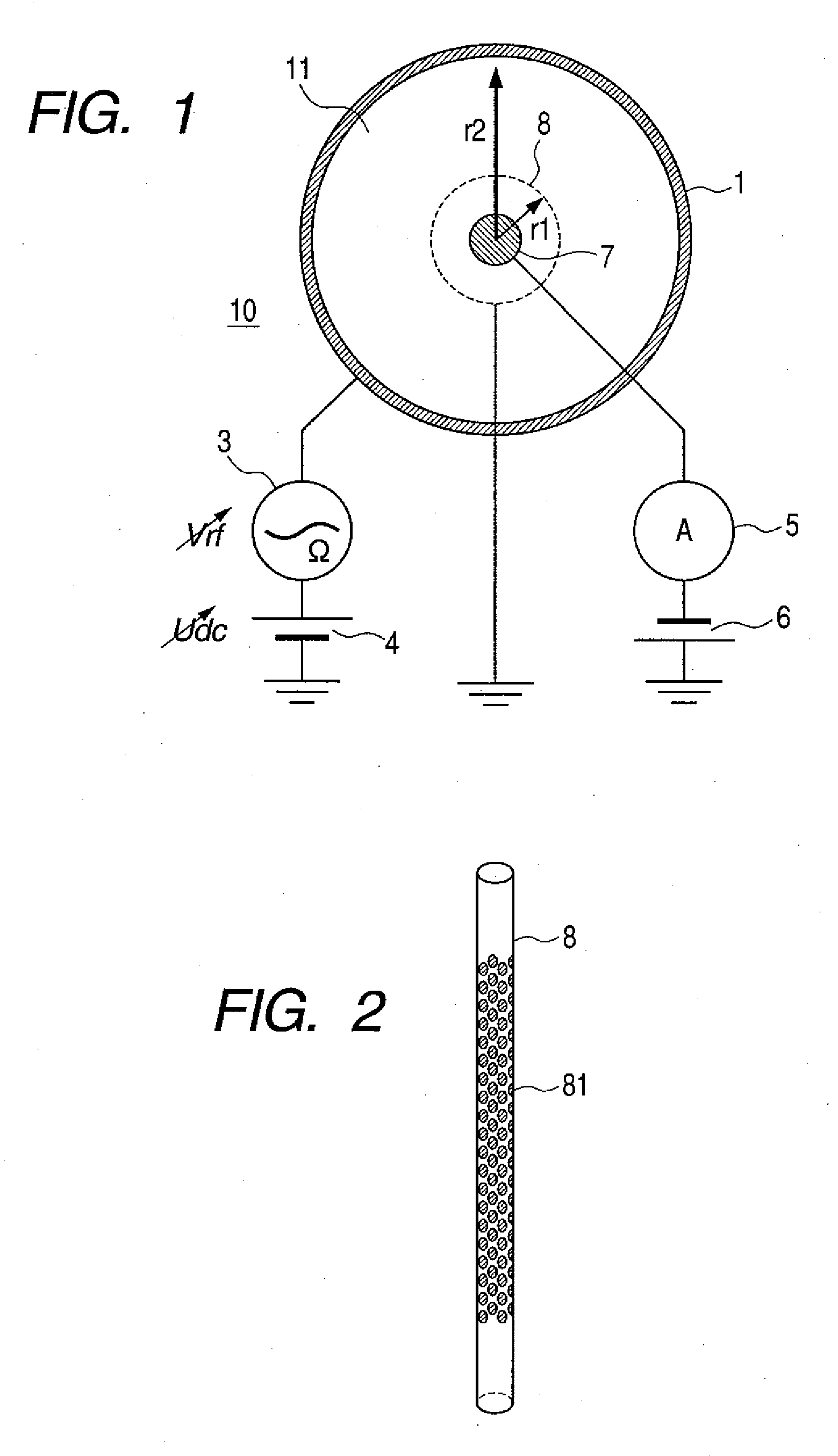
[0019]The first embodiment of this invention is described next while referring to the present invention. FIG. 1 is a drawing for describing an example of the basic circuit and the electrode structure of the one dimensional ion trap of this embodiment. The example shown here utilizes a hollow-cylindrical one dimensional ion trap 10, and is described by utilizing a cross sectional view intersecting the center axis of that ion trap 10.
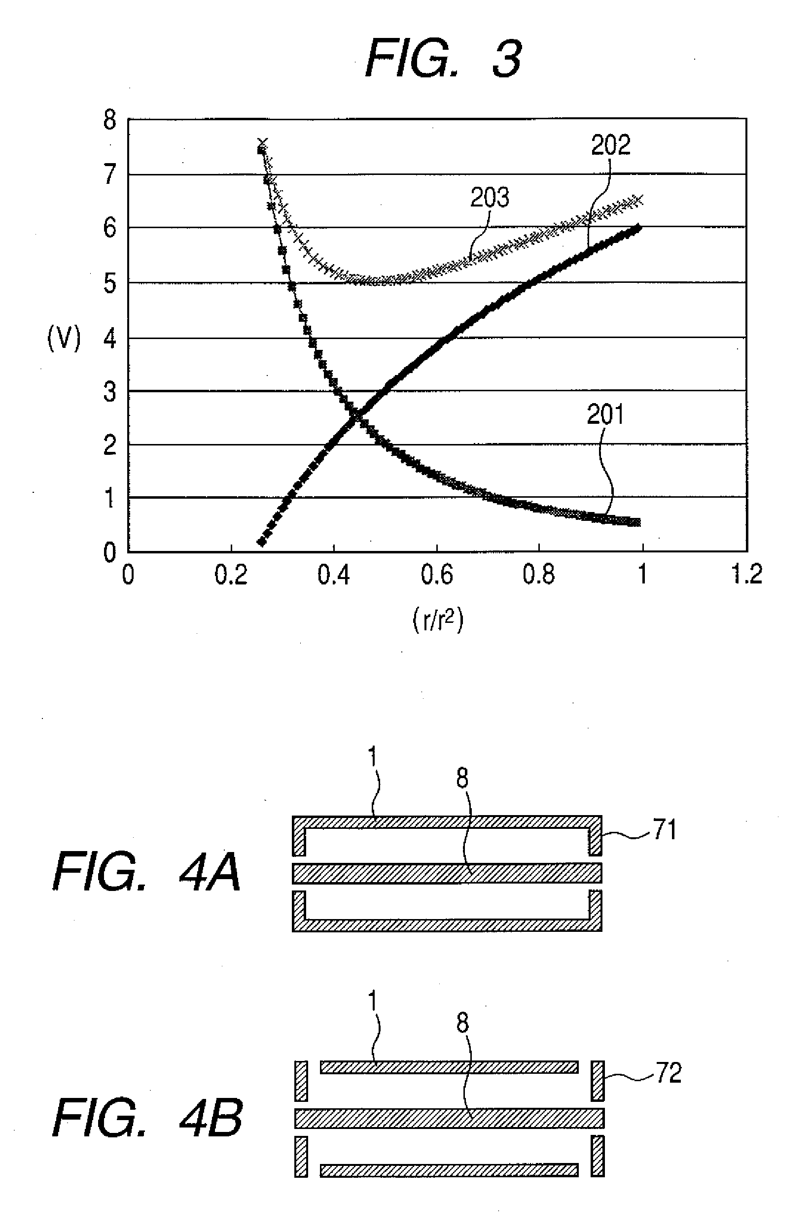
[0020]As shown in this drawing, the one dimensional ion trap 10 of this embodiment includes a first electrode (hollow-cylindrical electrode: radius r2) 1, and a second electrode (mesh hollow-cylindrical electrode: radius r1 (r12) 8, and a third electrode (solid-cylindrical electrode) 7 installed on the inner side of the second electrode. The hollow-cylindrical electrode 1 and the mesh hollow-cylindrical electrode 8 and the Solid-cylindrical electrode 7 are each a hollow cylindrical shape, and are positioned along a joint center axis. An RF voltage (amplit...
second embodiment
[0061]The second embodiment of this invention is described next. Here the one dimensional ion trap 10 of the first embodiment utilized in the mass spectrometer makes use of ion instability brought about by trap conditions. Namely, the voltage conditions of stably trapped ions are changed to bring about an unstable state, and the ions made to strike the Solid-cylindrical electrode 7 (selectively according to mass) at each mass-to-charge ratio (m / z). The electrical current resulting from the collision is measured by the ammeter 5, and the mass and mass-to-charge ratio (m / z) of the trapped ions are measured.
[0062]In order to selectively pass the ions trapped in the one dimensional ion trap 10 through the mesh hollow-cylindrical electrode 8 according to their mass, at least one of either the static voltage Udc and the amplitude of the RF waves applied by the RF voltage Vrf is changed as described in the first embodiment.
[0063]A structural drawing of the mass spectrometer 40 of this embo...
third embodiment
[0089]The third embodiment of this invention is described next. The one dimensional ion trap 10 of the first embodiment is utilized here for measuring ion mobility (extent of ion movement). The structure of the equipment is fundamentally the same as shown for the second embodiment in FIG. 5 through FIG. 7.
[0090]The method for measuring ion mobility by using the one dimensional ion trap 10 of this embodiment is described next. The mass-to-charge ratio (m / z) of the ion type forming the target is first of all isolated using the technique described in the first embodiment. Mass spectroscopy and measurements may then be made at the mass-to-charge ratio (m / z) of the ion type forming the target with the technique previously described in the second embodiment. A RF voltage Vrf that was set to a high amplitude is next applied so that these isolated ions are trapped in proximity to the outer side in the trapping space 11 of the one dimensional ion trap 10. Applying this RF voltage Vrf has the...
PUM
 Abstract
Description
Claims
Application Information
 - R&D
- Intellectual Property
- Life Sciences
- Materials
- Tech Scout
- Unparalleled Data Quality
- Higher Quality Content
- 60% Fewer Hallucinations
Browse by: Latest US Patents, China's latest patents, Technical Efficacy Thesaurus, Application Domain, Technology Topic, Popular Technical Reports.
© 2025 PatSnap. All rights reserved.Legal|Privacy policy|Modern Slavery Act Transparency Statement|Sitemap|About US| Contact US: help@patsnap.com


