Image Intensifying Device

a technology of intensifying device and light source, which is applied in the direction of instruments, electron multiplier details, cathode ray tube/electron beam tube, etc., can solve the problem that the light being viewed is too dim to be seen with natural human vision

Active Publication Date: 2009-10-15
ARRADIANCE LLC
View PDF16 Cites 17 Cited by
  • Summary
  • Abstract
  • Description
  • Claims
  • Application Information

AI Technical Summary

Problems solved by technology

In some applications of image intensifying devices, the light being viewed is too dim to be seen with natural human vision.

Method used


Image

  • Image Intensifying Device
  • Image Intensifying Device
  • Image Intensifying Device

Examples


Embodiment Construction

[0013]Reference in the specification to “one embodiment” or “an embodiment” means that a particular feature, structure, or characteristic described in connection with the embodiment is included in at least one embodiment of the teaching. The appearances of the phrase “in one embodiment” in various places in the specification are not necessarily all referring to the same embodiment.

[0014]It should be understood that the individual steps of the methods of the present teachings may be performed in any order and / or simultaneously as long as the teaching remains operable. Furthermore, it should be understood that the apparatus and methods of the present teachings can include any number or all of the described embodiments as long as the teaching remains operable.

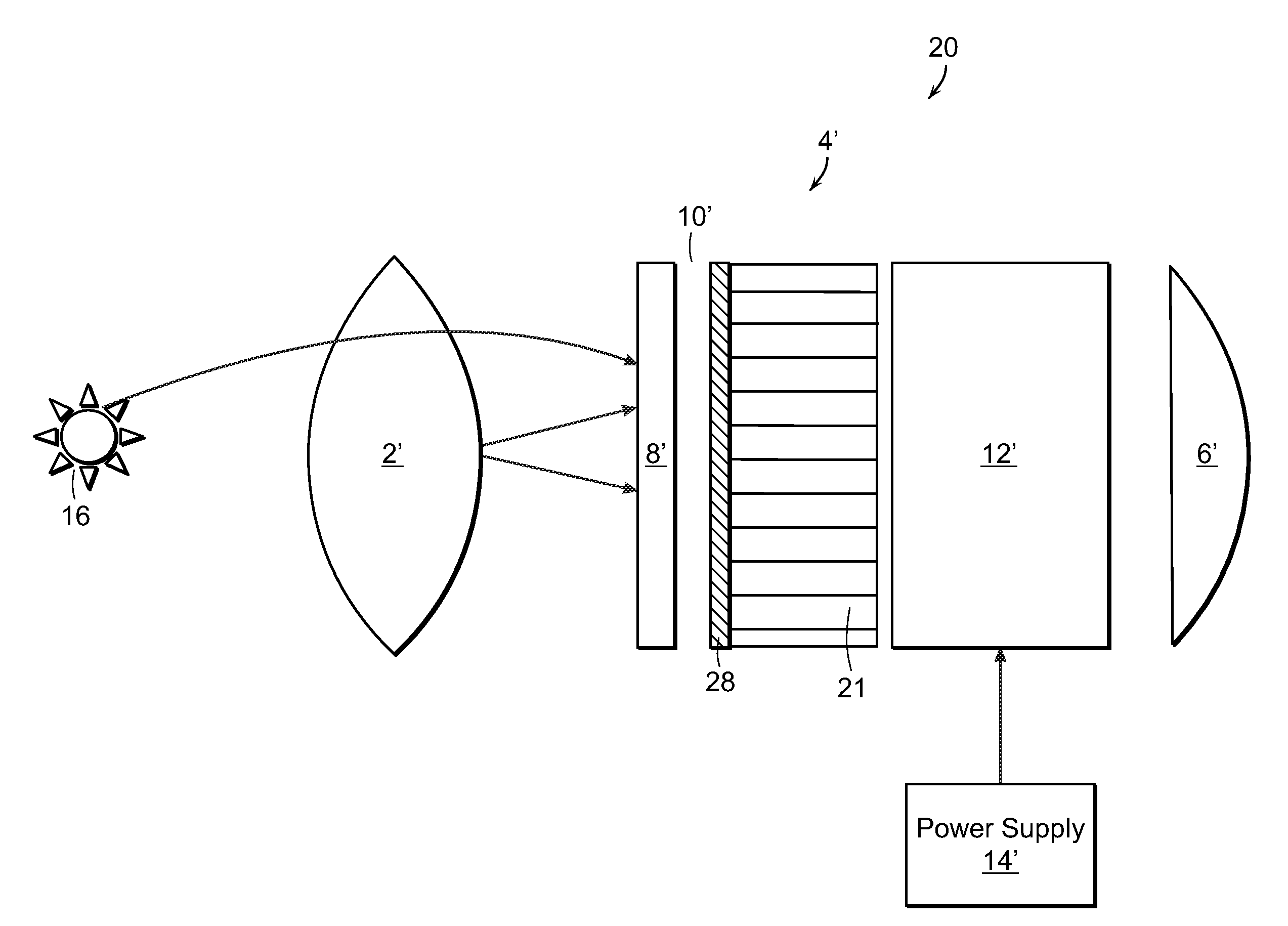
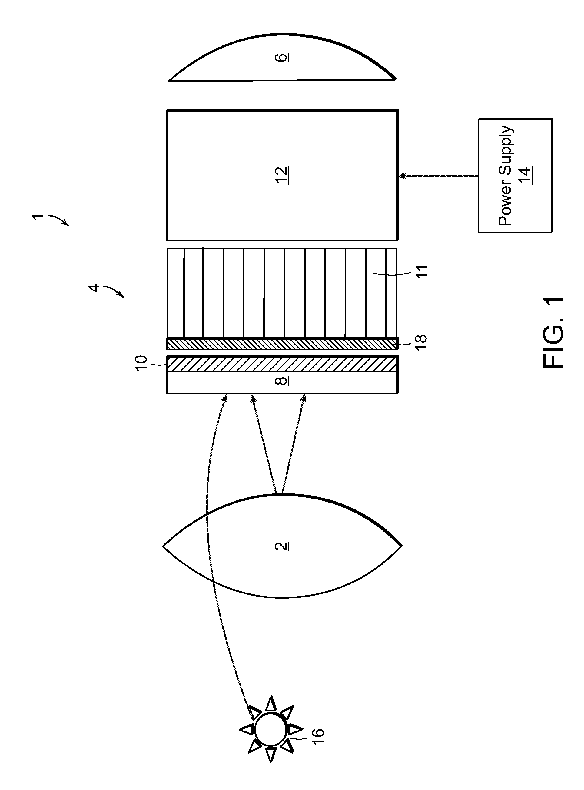
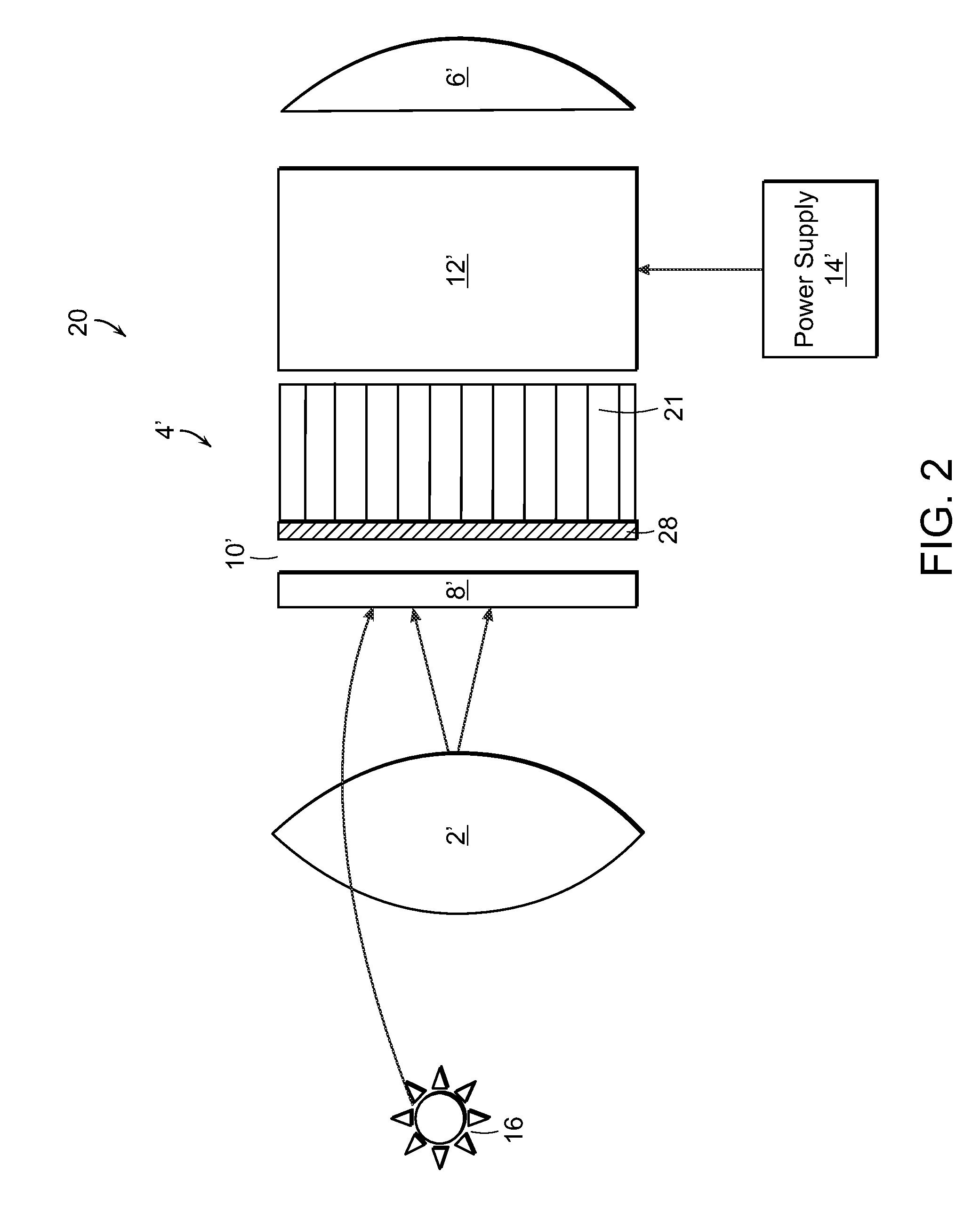
[0015]The present teachings will now be described in more detail with reference to exemplary embodiments thereof as shown in the accompanying drawings. While the present teachings are described in conjunction with various embodime...


PUM


Abstract

An image intensifying device includes a lens that is positioned at a light input that forms an image of a scene. The image intensifying device also includes an image intensifier tube that includes a photocathode that is positioned to receive the image formed by the lens. The photocathode generates photoelectrons in response to the light image of the scene. The image intensifier tube also includes a microchannel plate having an input surface comprising the photocathode. The microchannel plate receives the photoelectrons generated by the photocathode and generating secondary electrons. An electron detector receives the secondary electrons generated by the microchannel plate and generates an intensified image of the scene.

Description

CROSS-REFERENCE TO RELATED APPLICATIONS [0001]The present application is a non-provisional of copending U.S. Provisional Patent Application Ser. No. 61 / 043,993, filed on Apr. 10, 2008. The entire contents U.S. Patent Application Ser. No. 61 / 043,993 is herein incorporated by reference.INTRODUCTION [0002]The present teaching relates to image intensifying devices, such as night vision devices. In some applications of image intensifying devices, the light being viewed is too dim to be seen with natural human vision. Also, in some applications of image intensifying devices, the image being viewed is illuminated only by infrared light which is invisible to human vision. On nights that are too dark for natural human vision, invisible infrared light is provided by the stars of the night sky that is in the near-infrared portion of the electromagnetic spectrum. Infrared light is electromagnetic radiation having a wavelength that is longer than the wavelength of visible light, but shorter than...

Claims


Application Information

Patent Timeline
IPC IPC(8): H01J43/00
CPCH01J31/507H01J2231/5016H01J43/246
Inventor SULLIVAN, NEAL T.TREMSIN, ANTONSTENTON, KENDE ROUFFIGNAC, PHILIPPE
Owner ARRADIANCE LLC
Why Eureka
Try Eureka