
Quakeproof plinth to shelter a showpiece thereon

a technology for showpieces and plinths, which is applied in the field of plinths to shelter showpieces, can solve the problems of fragile objects such as the above-mentioned precious artistic works, easy to fall or fall down to fracture, and give esthetically adverse effects and bothering viewers, etc., and achieves the effects of reducing manufacturing costs, facilitating handling, and simplifying structur

Inactive Publication Date: 2009-10-15
MUSASHI +1
View PDF9 Cites 7 Cited by
  • Summary
  • Abstract
  • Description
  • Claims
  • Application Information

AI Technical Summary

Benefits of technology

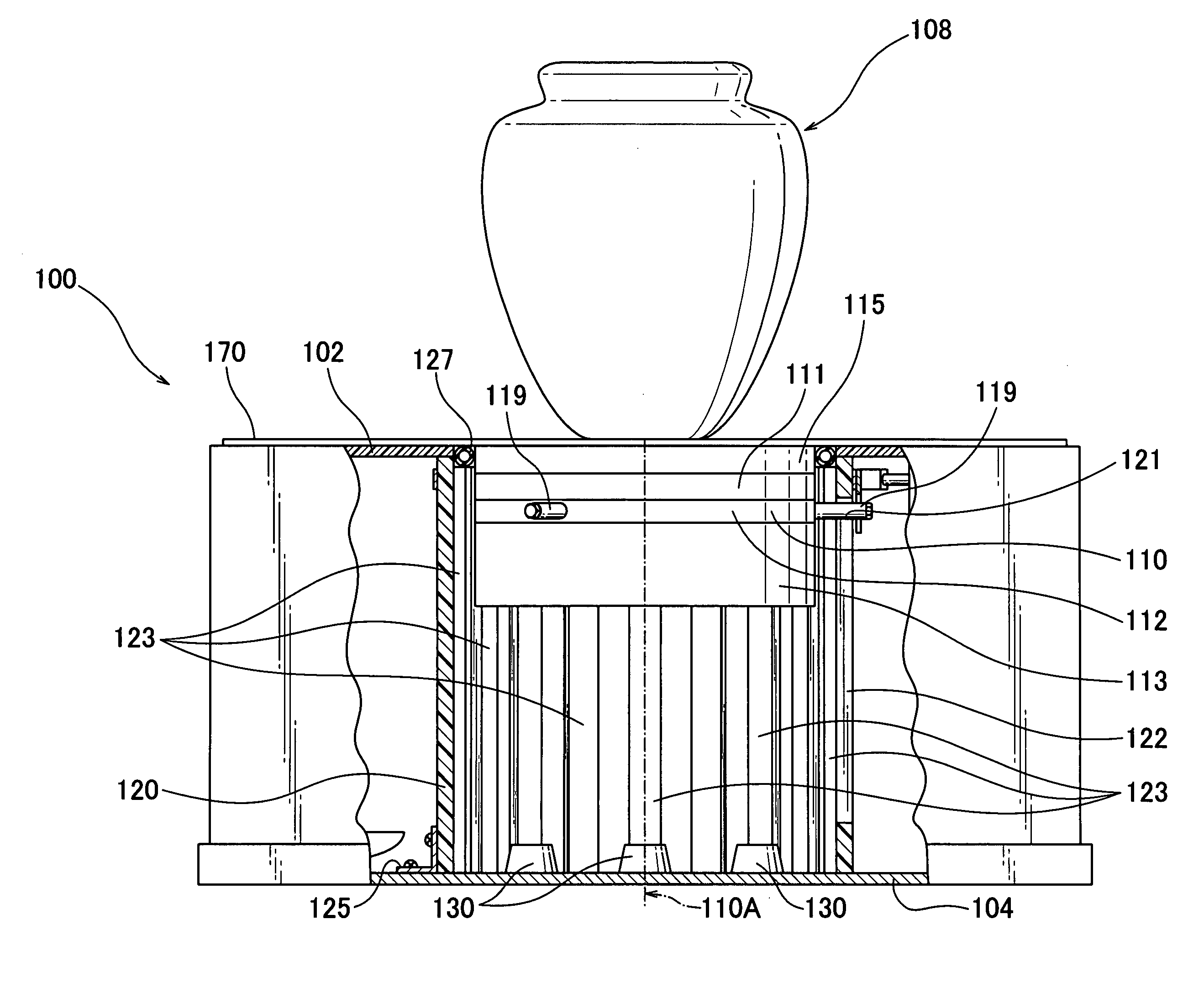
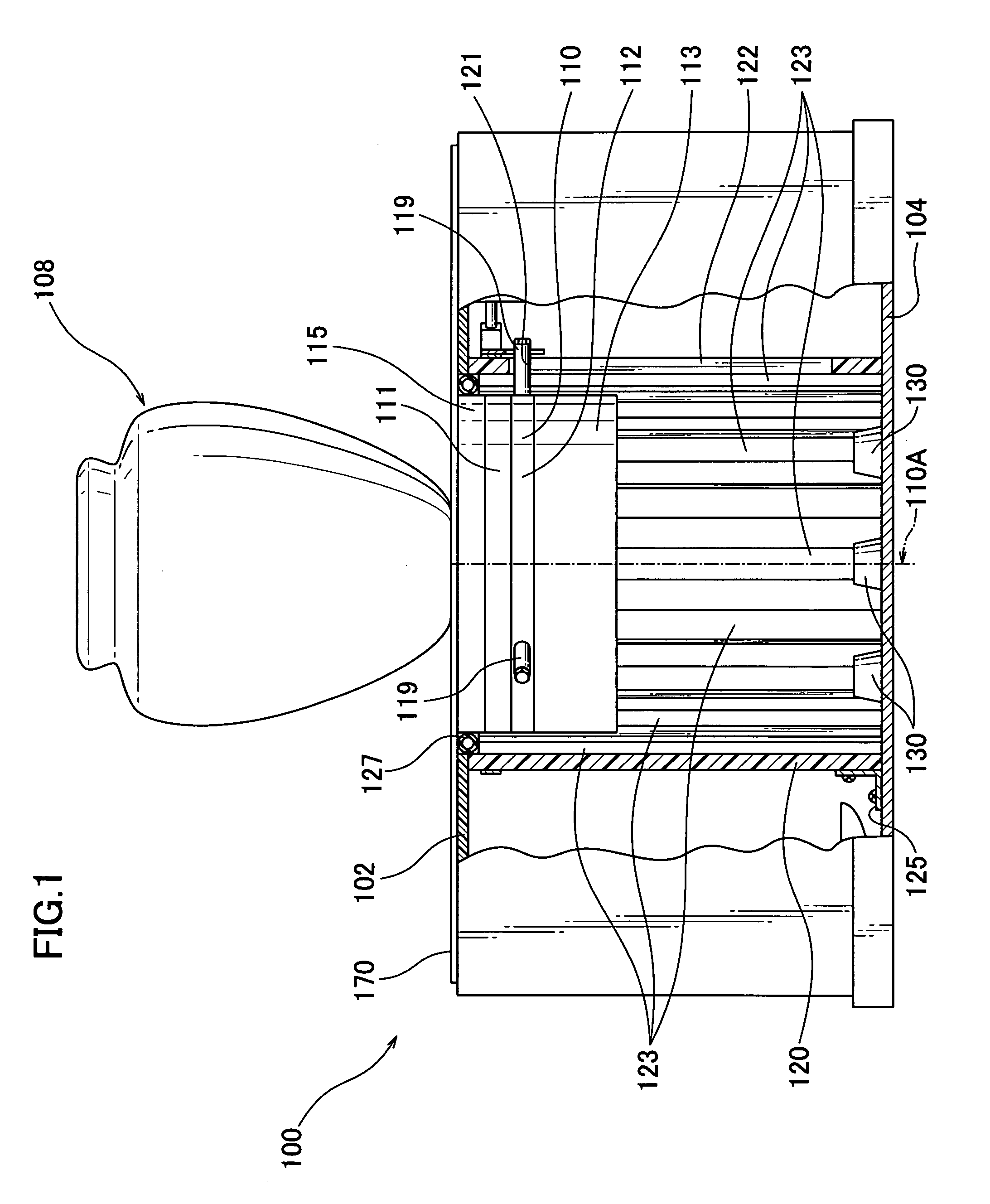
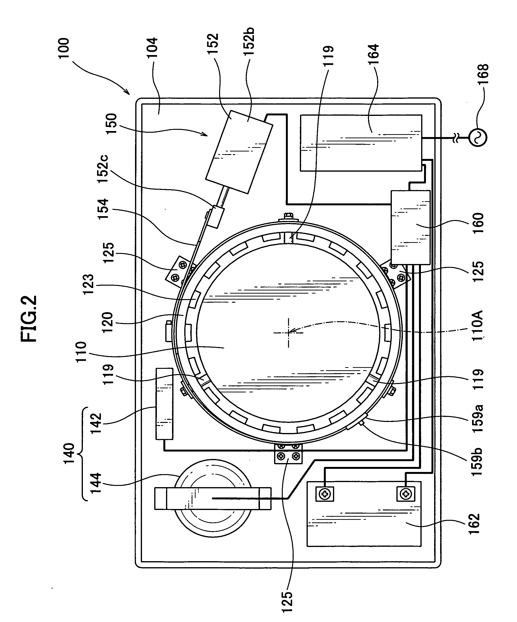
[0015]An earthquake-proof plinth according to the present invention is comprised of a showpiece mount on which a showpiece is seated, a supporting member capable of moving the showpiece mount upward and downward through the same, a shock-absorbing member located at the bottom of and inside of the supporting member to enable the showpiece mount to be shock-absorbingly bumped down thereon, a vibration detector for detecting vibrations exerted on the plinth, and an actuating device moving the showpiece mount downward in response to a detection signal from the vibration detector. Configured in this manner, the plinth can keep the showpiece thereon upright on exhibit, and is capable of assuredly protecting the showpiece from vibration caused by an earthquake. Since the plinth according to the present invention can make the showpiece mount go down along with the showpiece seated upright thereon, the showpiece can avoid tumbling and being damaged, and impact on the entire showpiece can be buffed, which resultantly ensures sheltering the showpiece.
[0016]Preferably, the plinth according to the present invention has a shock-absorbing member located at least one of upper and lower major surfaces of the showpiece mount; the shock-absorbing member being of any material compressively deformable upon impact. It is also preferable that the plinth according to the present invention has a shock-absorbing member located at the bottom of and inside of the supporting member on which the showpiece mount is to be bumped down; the shock-absorbing member being of any material compressively deformable upon impact. Configured in this way, the plinth ensures sheltering the showpiece at the onset of vibrations caused by an earthquake or the like.

Problems solved by technology

Fragile articles such as the above-mentioned precious artistic work, left in a cabinet, a whatnot, or a showcase, are prone to tumble or fall down to fracture because of a shake by an earthquake.
However, such manners are unsatisfactory as a full protection means from articles' tumbling or falling down.
They also give esthetically adverse effects as well as bothering obstacles to viewers.
In the earthquake-proof plinths as disclosed in Patent Document 1, when the showpiece is released from the holder and gravitationally dropped into the trap with shock-absorbing material such as sponge, the showpiece received at the bottom of the trap is prone to make a large bumping noise or even be damaged.
Also, this type of the prior art plinth is not capable of keeping showpiece mount without a tilt, and therefore, the showpiece is prone to have its finished surface, edges, and / or flourishes chipped or cracked upon being gravitationally dropped.
In the earthquake-proof plinth as disclosed in Patent Document 2, the elastic sac is an essential component, and the actuating device for the shutters is complicated in structure.
In addition, this type of the prior art plinth encounters difficulties that a showpiece cannot be kept without a tilt on exhibit and that vertical dimensions of the plinth cannot be reduced.
In the prior art plinth as disclosed in Patent Document 3, since the base plate is supported by the shaft, it is hard to keep the showpiece horizontal on exhibit, and it is also hard to reduce vertical dimensions of the plinth.
In addition, this type of plinth inevitably has an actuating device complicated in structure.

Method used


Image

  • Quakeproof plinth to shelter a showpiece thereon
  • Quakeproof plinth to shelter a showpiece thereon
  • Quakeproof plinth to shelter a showpiece thereon

Examples


Embodiment Construction

Best Mode of the Invention

[0031]

[0032]Preferred embodiments of a plinth according to the present invention will now be described in conjunction with the accompanying drawings.

[0033]Referring to FIG. 1, the plinth 100, which is adapted to shelter a showpiece seated thereon at the onset of a shake due to an earthquake or the like, comprises a block 102 housing components of the plinth, and a bottom plate 104 in the lowest portion of the block 102. The block is a hollow box-shaped table. In FIG. 1, the block 102 has its top plan cross-section shaped in rectangle. The top plan cross-section may be rectangular, polygonal, circular, or any other form defined by at least one of straight and curved lines.

[0034]A length of the block 102 may range from 350 to 800 mm. A width of the block 102 may range from 250 to 500 mm. A height of the block 102 may range from 160 to 400 mm. In some preferred embodiments, the block 102 may be 450 mm in length, 375 mm in width, and 220 mm in height. The block...


PUM


Abstract

A quakeproof plinth is adapted to make a showpiece mount vertically go down without a tilt so as to cushion and shelter a showpiece seated thereon from impact force exerted on the entire showpiece. A plinth (100) of the present invention is comprised of a showpiece mount (110), a supporting member (120) capable of supporting the showpiece mount so as to move the same upward and downward, basement shock absorbers (130) enabling the showpiece mount to be shock-absorbingly bumped down thereon, a vibration detector (140), and an actuating device (150) activated to move the showpiece mount downward in response to a detection signal produced from the vibration detector.

Description

FIELD OF THE INVENTION[0001]The present invention relates to a plinth to shelter a showpiece seated thereon in response to a shake caused externally. More particularly, the present invention relates to a quakeproof plinth to prevent a showpiece thereon from fracturing because of its tumbling or falling down in the event of exhibitions where articles of historically and artistically precious work, expensive chinaware, and / or esthetic handicraft such as glass-art ware are displayed in a museum, a reception room cabinet, or a showcase in a shop or a showroom.BACKGROUND ART[0002]Fragile articles such as the above-mentioned precious artistic work, left in a cabinet, a whatnot, or a showcase, are prone to tumble or fall down to fracture because of a shake by an earthquake. Usually, the articles are guarded by strained rope or bracing that surrounds the articles. As to a particularly large artwork showpiece, several strings of rope are typically strained and separated by a certain distance...

Claims


Application Information

Patent Timeline
Patent Type & Authority Applications(United States)
IPC IPC(8): F16M11/00F16M13/00
CPCA47F3/00
Inventor KANEKO, TOMONAOYAMANE, NOBORU
Owner MUSASHI
Learn More