Parallel mechanism

a technology of parallel mechanism and ball joint, which is applied in the direction of mechanical control devices, gearing, instruments, etc., can solve the problems of ball joint wear, ball may loose from the socket, increase a load, etc., and achieve the effect of ensuring the maintainability of the parallel mechanism

Inactive Publication Date: 2009-10-15
MURATA MASCH LTD
View PDF49 Cites 8 Cited by
  • Summary
  • Abstract
  • Description
  • Claims
  • Application Information

AI Technical Summary

Benefits of technology

[0017]In this arrangement, the length of the extending portion can be appropriately set. Thus, the b...

Problems solved by technology

Thus, when the ball joint is subjected to a load exceeding the tensile force of the spring, the ball may come loose from the socket.
This problem is more significant at a positio...

Method used


Image

  • Parallel mechanism
  • Parallel mechanism
  • Parallel mechanism

Examples


Embodiment Construction

[0024]Preferred embodiments of the present invention will be described below in detail with reference to the drawings. In the drawings, the same elements are denoted by the same reference numerals, and duplicate descriptions are omitted.

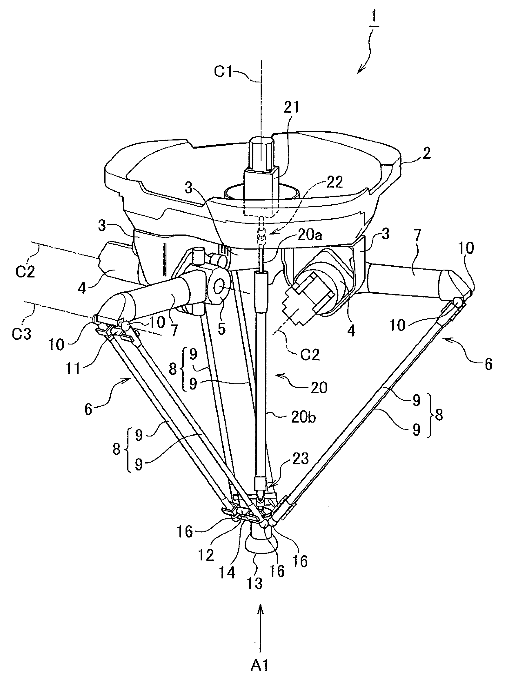
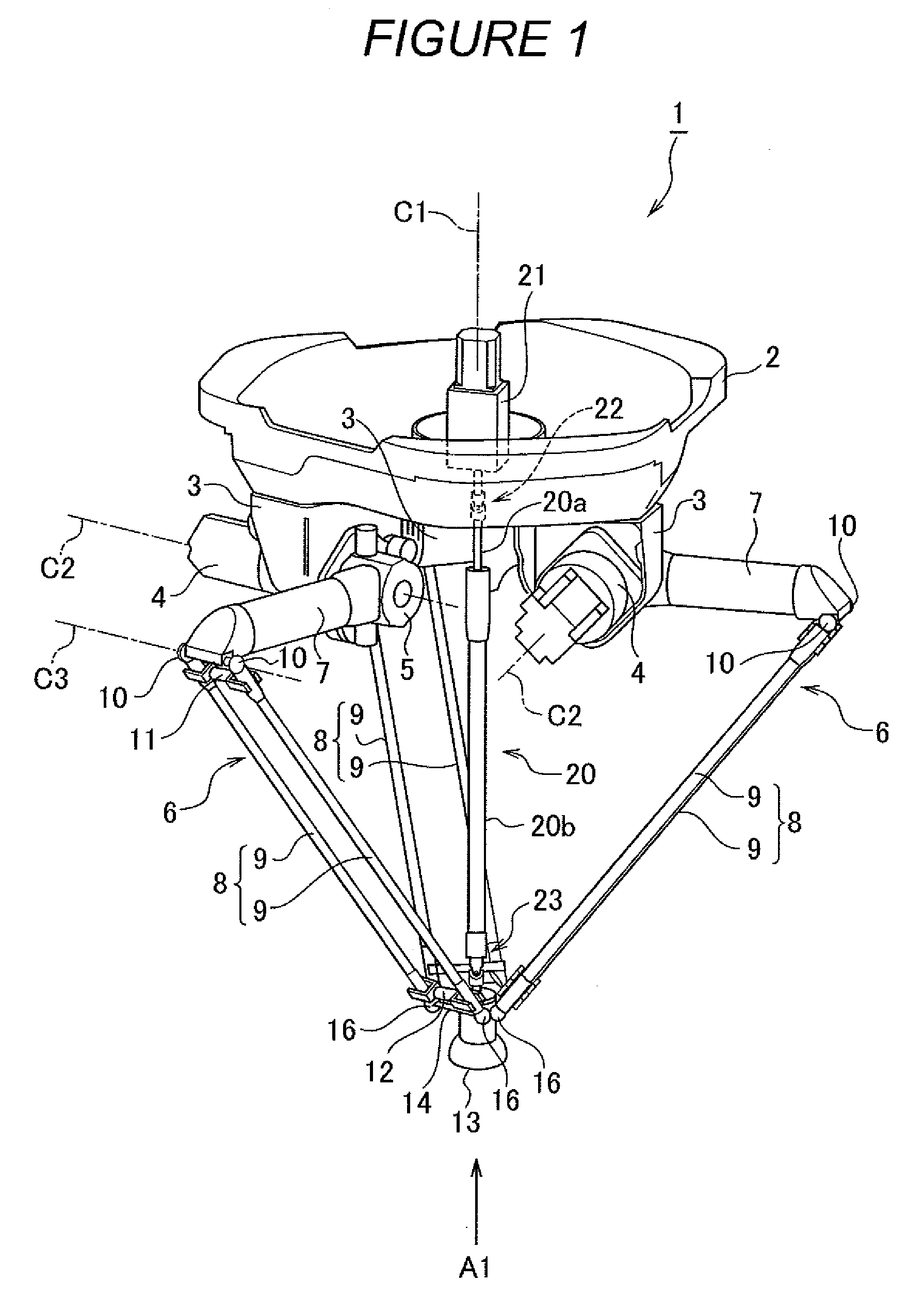
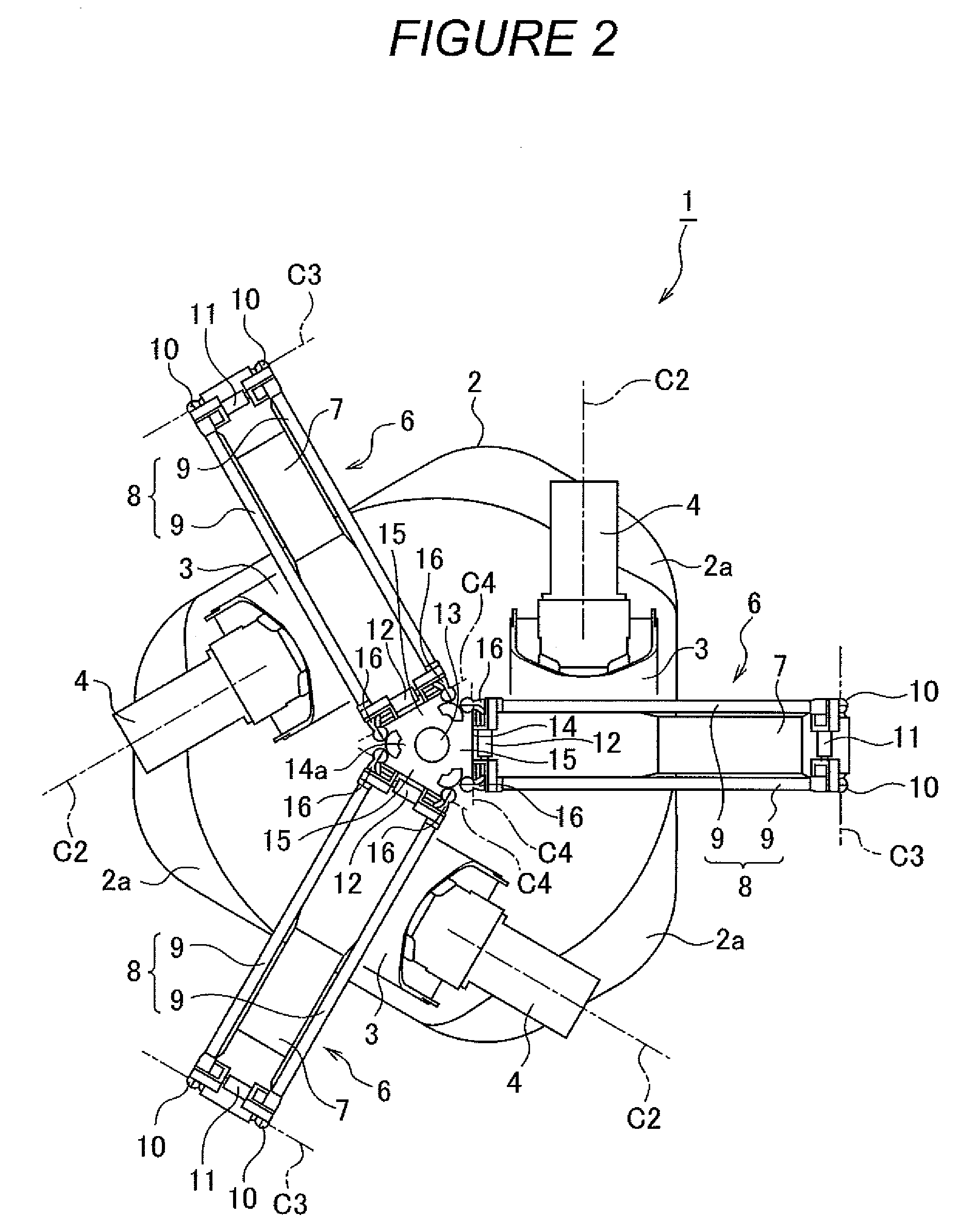
[0025]First, the general configuration of a parallel mechanism according to a preferred embodiment will be described with reference to FIGS. 1 and 2. FIG. 1 is a perspective view showing the general configuration of the parallel mechanism 1 according to a preferred embodiment of the present invention. FIG. 2 is a diagram showing the parallel mechanism 1 as viewed from the direction of arrow A1 in FIG. 1.

[0026]The parallel mechanism 1 has a base portion at the top thereof. The parallel mechanism 1 is supported by fixing a flat mounting surface 2a of the base portion 2 arranged on the bottom surface side thereof, to, for example, a flat ceiling. On the other hand, three support members 3 are provided on the bottom surface side of the base portion 2. An...


PUM


Abstract

A parallel mechanism has a plurality of arms. Each of the arms has a ball joint. The ball joint includes a ball stud with a shaft portion and ball-shaped head, and a socket swingably and pivotally movably holding the ball-shaped head of the ball stud. The socket includes a semispherical recess portion holding the ball-shaped head from a top portion to an equator thereof, and an extending portion which is smoothly continuous with the semispherical recess portion and which extends from the equator of the ball-shaped head to the shaft portion side. The inner diameter of an opening in the extending portion is equal to or larger than the diameter of the ball-shaped head.

Description

CROSS-REFERENCE TO RELATED APPLICATIONS[0001]This application claims priority under 35 U.S.C. 119 to Japanese Patent Application No. 2008-102966, filed on Apr. 10, 2008, which application is hereby incorporated by reference in its entirety.BACKGROUND OF THE INVENTION[0002]1. Field of the Invention[0003]The present invention relates to a parallel mechanism, and in particular, to a parallel mechanism including arms coupled together via a ball joint.[0004]2. Description of Related Art[0005]A conventionally known parallel mechanism includes a base portion that is a support base and a bracket with an end effector attached thereto coupled together in parallel via a plurality of arms. In the parallel mechanism, electric motors are arranged in parallel. Furthermore, a plurality of arms coupled to the respective motors ultimately operate one bracket.[0006]In the parallel mechanism, each of the arms is composed of a link and rods. The link and each of the rods are coupled together via ball jo...

Claims


Application Information

Patent Timeline
IPC IPC(8): B25J18/00
CPCB25J9/108B25J17/0266Y10T74/20341B25J9/0051B25J17/0283B23Q1/44B23Q1/70B25J11/00F16H21/46
Inventor NISHIDA, TATSUHIKONAKANISHI, HIDEAKIYAMASHITA, MANABU
Owner MURATA MASCH LTD
Why Eureka
Try Eureka