
System and method for corneal astigmatic axis marking

a marking system and astigmatic axis technology, applied in the field of ocular marking system and method, can solve the problems of blurred image, introduction of several significant errors, and ultimately blindness, and achieve the effect of improving the outcome of astigmatic refractive surgery

Inactive Publication Date: 2009-10-08
DAVIS ANDREW
View PDF21 Cites 36 Cited by
  • Summary
  • Abstract
  • Description
  • Claims
  • Application Information

AI Technical Summary

Benefits of technology

"The present invention provides a new system and method for marking the astigmatic axis of the eye while a patient is sitting prior to eye surgery. This is done using a corneal marker that is weighted to align with the corneal surface of the eye. The marker has a cylindrical central hub and a plurality of radial blades that can leave a perceptible impression or apply ink to the corneal surface. The method involves adjusting the marking device, illuminating the eye, retracting the eyelid, and observing the corneal light reflex to align the marking device. The invention improves the accuracy of astigmatic refractive surgeries and enhances the outcome of surgery."

Problems solved by technology

This causes the light rays to be bent differently, which causes the image to be blurred.
Blindness ultimately can result.
This two-step methodology has several shortcomings and introduces several significant sources of error.
In particular, error is introduced when the surgeon uses the alignment reference marks made in the first step to then mark the astigmatic axis in the second step.
If the eye movement is not taken into consideration when the patient lies down the direction of the axis of astigmatism will not be properly accounted for.
Finally, the change in orientation encountered with the patient lying down with surgeon now approaching the patient from the side or from the forehead can be inherently confusing when attempting to mark the axis which was measured with the patient sitting.
Difficulty with centration and rotation compound the multiple errors already introduced.
While this system reduces disadvantages associated with traditional hand-held devices, however, the use of a trial frame apparatus can be cumbersome.

Method used


Image

  • System and method for corneal astigmatic axis marking
  • System and method for corneal astigmatic axis marking
  • System and method for corneal astigmatic axis marking

Examples


Embodiment Construction

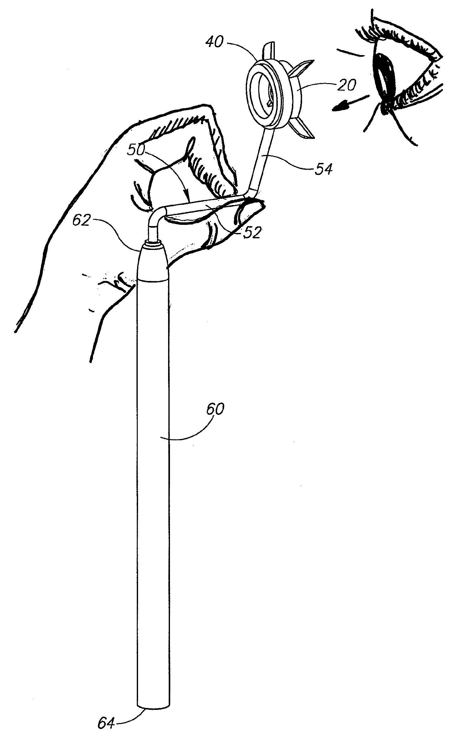
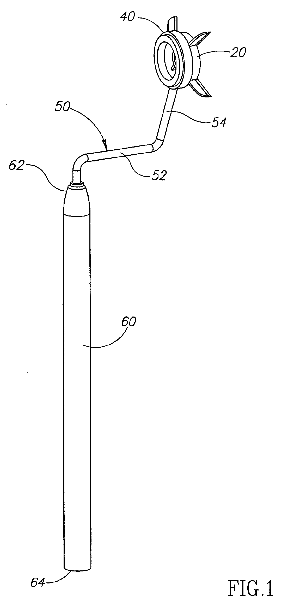
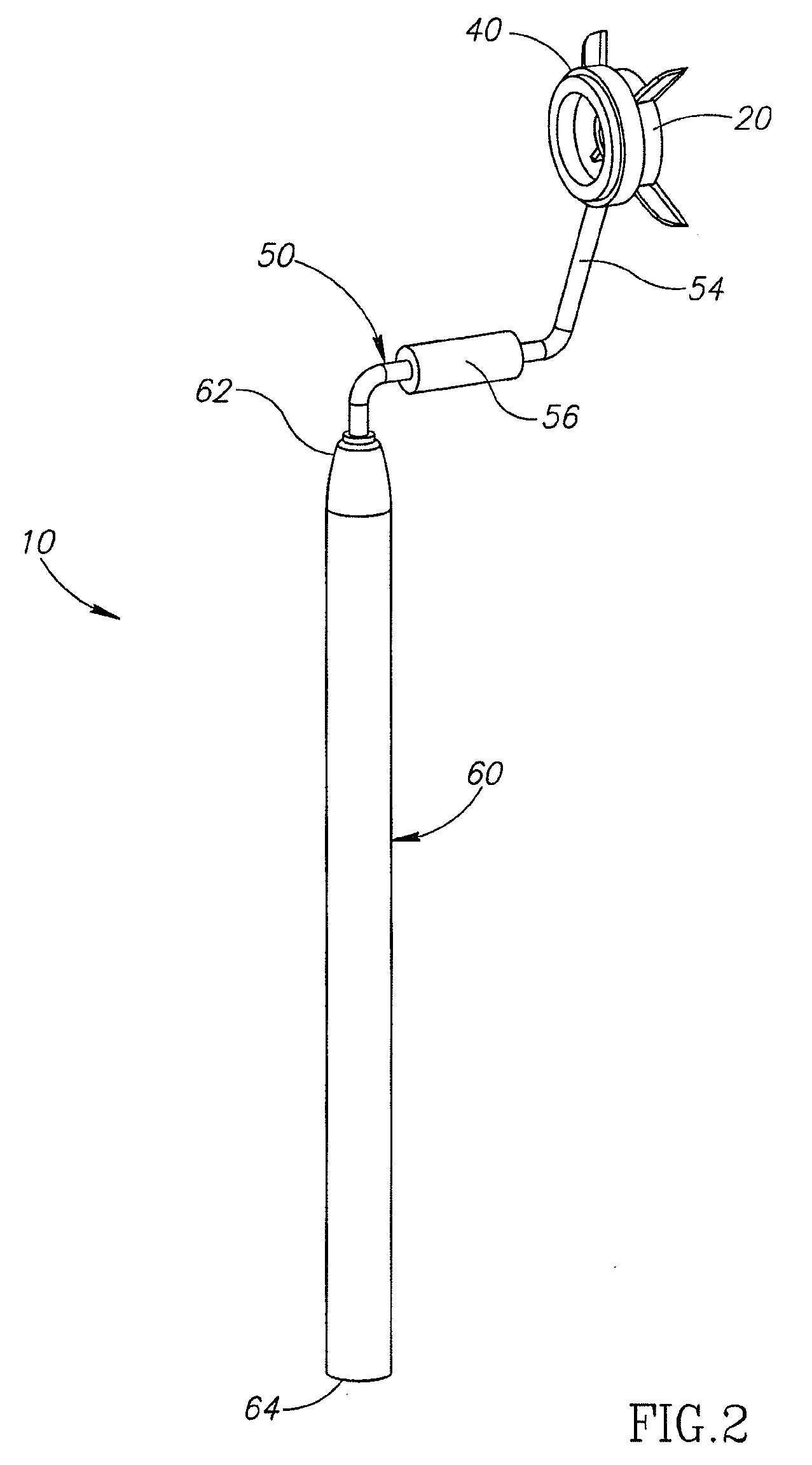
[0029]A description of the preferred embodiments of the present invention is presented with reference to FIGS. 1-9. FIG. 1 shows one embodiment of a corneal marking device 10 of the present invention. The corneal marking device 10 includes a corneal marker 20, a ring gauge 40, a handle 50 and a weighted stem 60. The preferred weighted stem 60 includes a proximate end 62 located near the handle 50 and a distal end 62 located remote to the handle 50. The stem 60 may be of varying lengths or thickness, but is preferably of sufficient weight to facilitate orientation of the handle 50 to a patient's eye under examination when in operation, but not so heavy to be uncomfortable for the surgeon during operation of the corneal marking device 10.

[0030]The handle 50 is preferably sized to fit comfortably within a surgeon's hand, but may be of varying lengths or thickness. The handle 50 is attached to the proximate end 62 of the stem 60 and extends away from the stem to support the corneal mark...


PUM


Abstract

The present invention includes a corneal marker having an adjustable element providing for orientation of the marker to the astigmatic axis of a patient's eye under examination, a handle secured to the corneal marker and a stem secured to and extending below the handle. The stem is weighted to facilitate alignment of the corneal marker to the corneal surface of the patient's eye under examination during corrective eye surgery according to the corneal light reflex from the eye in response to an illumination source.

Description

PRIORITY CLAIM[0001]This application claims priority from earlier filed U.S. Provisional Patent Application Ser. No. 61 / 072,758 filed Apr. 2, 2008. The foregoing application is hereby incorporated by reference in its entirety as if fully set forth herein.FIELD OF THE INVENTION[0002]This invention relates generally to an ocular marking system and method and, more specifically, a corneal marking system and method to mark the astigmatic axis on the corneal surface of the eye prior to a surgical procedure to correct the ocular condition of astigmatism.BACKGROUND OF THE INVENTION[0003]Astigmatism, an optical defect which blurs vision, is usually caused by an irregular curvature of the cornea. In a perfectly shaped eye, the cornea is spherical, and bends all incoming light in the same way, producing a sharply focused image on the back of your eye (retina). In individuals with astigmatism, the cornea is asymmetrically curved, similar to the surface of a football, with one axis of the ball ...

Claims


Application Information

Patent Timeline
Patent Type & Authority Applications(United States)
IPC IPC(8): A61F9/007
CPCA61F9/0136
Inventor DAVIS, ANDREW
Owner DAVIS ANDREW
Learn More