
Self-calibrating gradient dilution in a constituent assay and gradient dilution apparatus performed in a thin film sample

Inactive Publication Date: 2009-10-08
ABBOTT POINT CARE
View PDF41 Cites 13 Cited by
  • Summary
  • Abstract
  • Description
  • Claims
  • Application Information

AI Technical Summary

Benefits of technology

[0011]It is therefore an object of this invention to provide a method and apparatus wherein mixing and diffusion are used to create a concentration gradient between two or more miscible liquids in a thin film sample in a chamber so that the equilibrium in the thin dimension of the chamber is very rapid and concentration differences in the long axis of the chamber do not reach equilibrium during the time of the assay, and the final relative inter-dilution being measured by the relative concentration of a sensible marker which does not participate in any of the desired chemical reactions and whose properties are such that it allows its accurate measurement at any point in the reaction chamber.

Problems solved by technology

Conditions where the prozone effects occur can result in false negatives and falsely low results with catastrophic results to the patient.
Although these can be very accurate, they require careful calibration and greatly add to the complexity of automated instrumentation.
Additionally the range of analyte present in the sample may exceed the dynamic range of the assay and may require further dilution of the sample for accurate results.
Another problem with such assays is that the end-points are sometimes difficult to determine, thus adding a significant error to the titer determination.
Automation can increase the test efficiency and accuracy, but performing the dilutions by an instrument is very difficult and time consuming including the need to first define the desired dilution which can vary from test to test and the multiple dilution steps are very complex.

Method used


Image

  • Self-calibrating gradient dilution in a constituent assay and gradient dilution apparatus performed in a thin film sample
  • Self-calibrating gradient dilution in a constituent assay and gradient dilution apparatus performed in a thin film sample
  • Self-calibrating gradient dilution in a constituent assay and gradient dilution apparatus performed in a thin film sample

Examples


Embodiment Construction

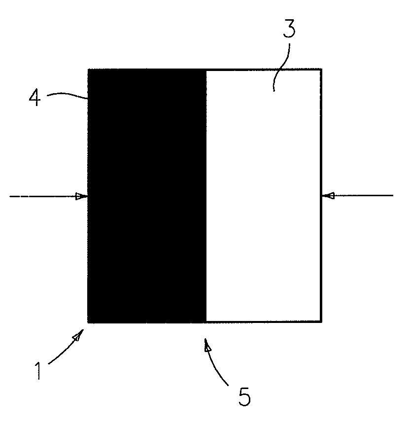
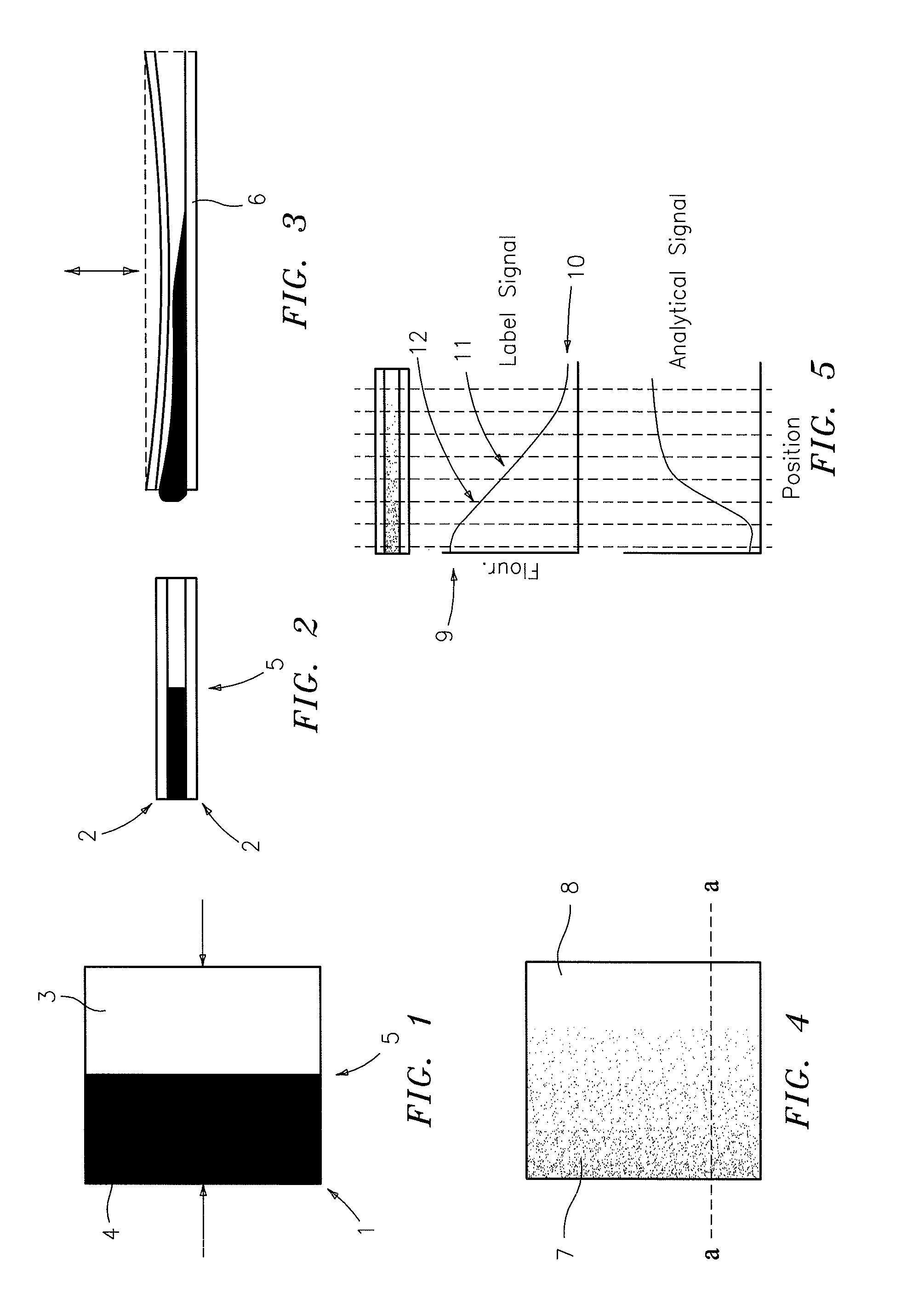
[0027]FIG. 1 is a schematic top view of a chamber 1, in this instance a square, whose cross-section is shown in FIG. 2. The chamber is comprised of relatively thin top and bottom plates, at least one of which must be transparent. Into the chamber are introduced two or more liquids, one being the sample 3 to be analyzed and the other being the reagent 4 required for the analysis. At least one of these liquids has a dissolved marker which may be fluorescent, such as fluorescence, or an absorbent dye, such as phenol red, or the like. The marker must be such that it does not chemically interfere with the desired analytical signal nor should the marker signal be affected by any signal or reaction products of the analysis in a manner which cannot be compensated for.

[0028]In the instance shown, liquid 4 is the analyzing reagent which contains a fluorescent marker, and liquid 3 is the sample to be analyzed. If the liquids are introduced into the chamber in equal amounts, in the directions i...


PUM


Abstract

A method and apparatus for measuring antibody titers in a thin film sample in an automated system which does not require multiple dilutions. The system provides a simple method for creating an in-situ dilution within a sample analysis chamber without the use of any precision fluid-handling components, and further, to use the same principles to provide a wide range of sample dilutions within the chamber so as to obviate the need for additional dilution steps when dealing with samples possibly containing wide ranges of analyte concentrations.

Description

[0001]This application claims the benefit of U.S. Provisional Application Nos.: 61 / 041,784, filed Apr. 2, 2008; 61 / 041,791, filed Apr. 2, 2008; 61 / 041,790, filed Apr. 2, 2008; 61 / 041,794, filed Apr. 2, 2008; 61 / 041,797, filed Apr. 2, 2008; and 61 / 043,571, filed Apr. 9, 2008.BACKGROUND OF THE INVENTION[0002]1. Technical Field[0003]This disclosure relates to methods and apparatus for measuring antibody titers in an automated system which does not require multiple dilutions. The system provides a simple method for creating an in-situ dilution within a sample analysis chamber without the use of any precision fluid-handling components, and further, to use the same principles to provide a wide range of sample dilutions within the chamber so as to obviate the need for additional dilution steps when dealing with samples possibly containing wide ranges of analyte concentrations.[0004]2. Background Information[0005]In most assays it is necessary to provide an exact dilution of the sample to b...

Claims


Application Information

Patent Timeline
IPC IPC(8): G06K9/00
CPCG01N21/6428G01N33/54373G01N33/48G01N33/5304G01N33/54386
Inventor WARDLAW, STEPHEN C.LEVINE, ROBERT A.
Owner ABBOTT POINT CARE
Learn More