Low orbit missile-shaped satellite for electro-optical earth surveillance and other missions

a satellite and low orbit technology, applied in the field of surveillance satellites, can solve the problems of large satellites, limited satellites in terms, and large satellites

Inactive Publication Date: 2009-10-08
RAFAEL ADVANCED DEFENSE SYSTEMS
View PDF10 Cites 27 Cited by
  • Summary
  • Abstract
  • Description
  • Claims
  • Application Information

AI Technical Summary

Benefits of technology

[0021]There is also provided according to the teachings of the present invention, a method for imaging the surface of the Earth comprising: (a) providing a satellite having: (i) an elongated satellite body having a direction of elongation, a length parallel to the direction of elongation and two transverse dimensions perpendicular to the direction of elongation and to each other, and (ii) an optical telescope arrangement deployed within the satellite body, a major part of the telescope arrangement having an optical axis substantially parallel to the direction of elongation, the telescope arrangement including a mirror arrangement deployed to direct a line of sight of the optical telescope in a direction lateral to the direction of elongation, the optical telescope arrangement having an optical aperture dimension, wherein each of the two transverse dimensions is not more than 50 percent greater than the optical aperture dimension; (b) propelling the satellite into an orbital path around the Earth at an altitude of between about 200 and about 500 kilometers; (c) maintaining the direction of elongation substantially parallel to a direction of motion of the satellite; and (d) employing the optical telescope arrangement to obtain images of the surface of the Earth.
[0022]Turning now to the definitions of various terms as used herein...

Problems solved by technology

These relatively high altitude orbits impose relatively large aperture optics to achieve a required ground resolution, resulting in satellite weight of several hundreds of kilograms.
As a result, these satellites are limited in term of observing several regions of...

Method used


Image

  • Low orbit missile-shaped satellite for electro-optical earth surveillance and other missions
  • Low orbit missile-shaped satellite for electro-optical earth surveillance and other missions
  • Low orbit missile-shaped satellite for electro-optical earth surveillance and other missions

Examples


Embodiment Construction

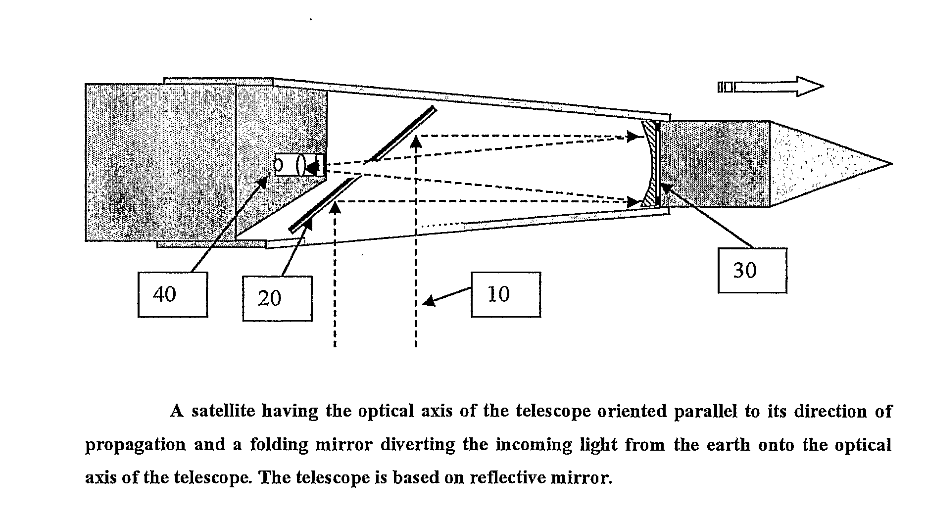
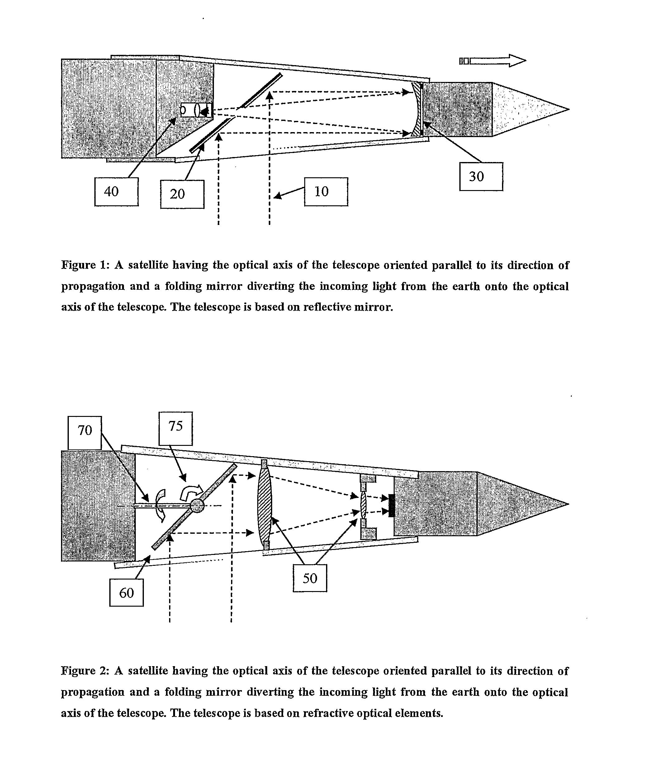
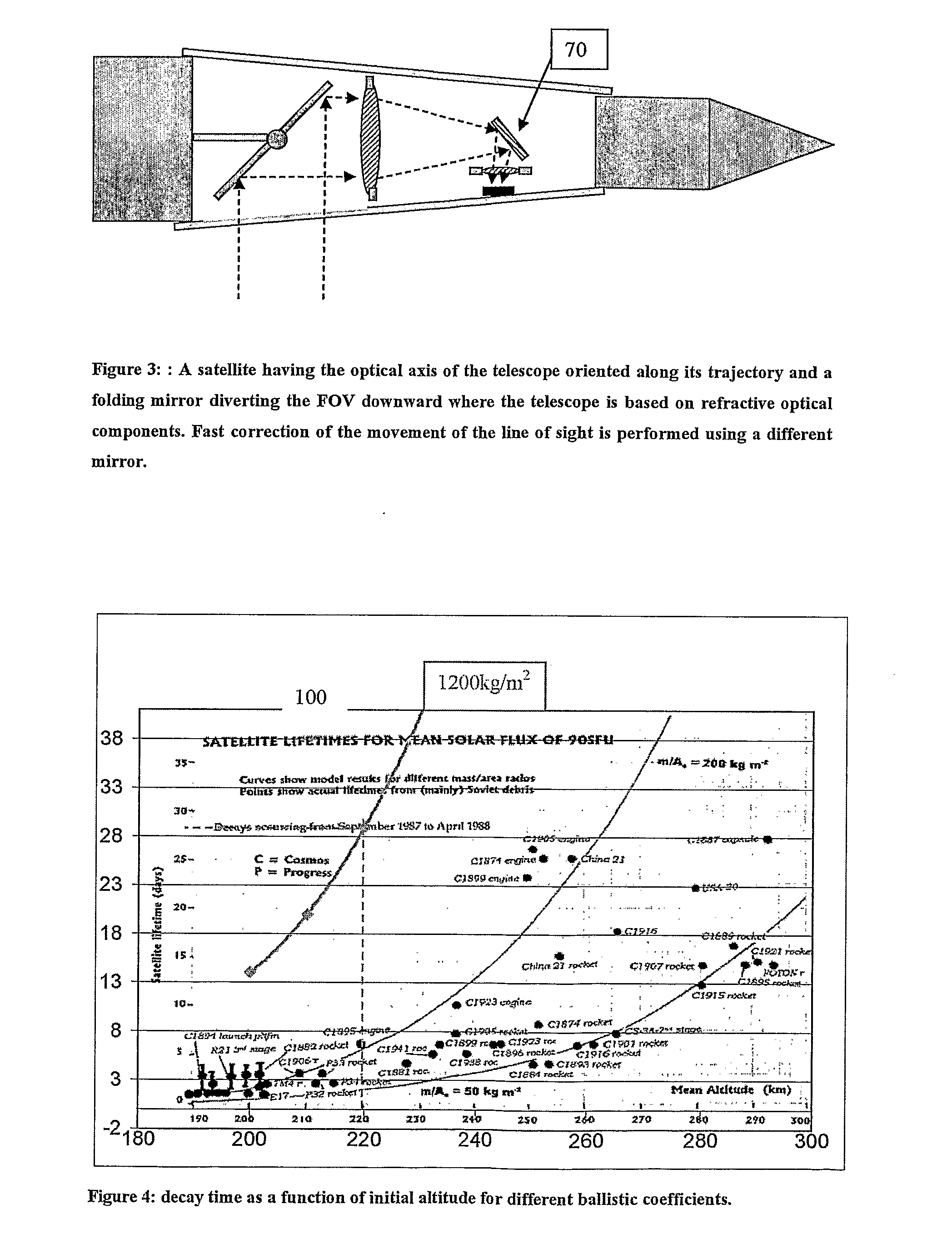
[0037]The present invention provides a low orbit optical imaging satellite has a long thin satellite body housing an optical telescope arrangement. A major part of the telescope arrangement has its optical axis roughly parallel to the direction of elongation and includes a mirror arrangement deployed to direct a line of sight of the optical telescope out sideways from the direction of elongation. The transverse dimensions of the satellite body are preferably minimized to be close to the optical aperture dimension of the optical telescope, thereby providing a high ballistic coefficient and high orbit lifetime for orbits in the low thermosphere. The transverse dimensions are preferably no more than 50 percent greater than the optical aperture dimension, and more preferably no more than 20 percent, or even 10 percent greater.

[0038]The present invention describes a high resolution, earth surveillance, “missile-shaped” satellite with very low cross section and very low drag. This satelli...


PUM


Abstract

A low orbit optical imaging satellite has a long thin satellite body housing an optical telescope arrangement. A major part of the telescope arrangement has its optical axis roughly parallel to the direction of elongation and includes a mirror arrangement deployed to direct a line of sight of the optical telescope out sideways from the direction of elongation. The transverse dimensions of the satellite body are preferably minimized to be close to the optical aperture dimension of the optical telescope, thereby providing a high ballistic coefficient and high orbit lifetime for orbits in the low thermosphere.

Description

FIELD AND BACKGROUND OF THE INVENTION[0001]The present invention relates to surveillance satellites and, in particular, it concerns a low orbit missile-shaped satellite for electro-optical earth surveillance and other missions.[0002]Earth surveillance satellites are usually designed to stay in high enough orbits (typically 350-800 km), where the residual atmospheric drag is negligible. Their specific shape and their cross section are therefore of no significant importance. These relatively high altitude orbits impose relatively large aperture optics to achieve a required ground resolution, resulting in satellite weight of several hundreds of kilograms. Changing a satellite orientation is a relatively slow process based on conservation of momentum using reaction wheels. As a result, these satellites are limited in term of observing several regions of interest during limited time interval. These satellites are usually designed to stay in orbit for several years, requiring very high re...

Claims


Application Information

Patent Timeline
IPC IPC(8): G02B23/02B64G1/24B64G1/10B64G1/40
CPCB64G1/1021B64G2001/1028G02B26/0816G02B23/06G02B23/02B64G1/1028
Inventor DANZIGER, YOCHAYMISHNE, DAVIDMILLER, NEHEMIA
Owner RAFAEL ADVANCED DEFENSE SYSTEMS
Why Eureka
Try Eureka