
Broadband Pilot Channel Estimation Using A Reduced Order FFT and a Hardware Interpolator

a pilot channel and hardware interpolator technology, applied in the field of channel estimation in communication systems, can solve the problems of undesirably large power consumption of receivers and noise reduction of signals, and achieve the effect of consuming less processing resources and less power

Inactive Publication Date: 2009-10-01
QUALCOMM INC
View PDF22 Cites 25 Cited by
  • Summary
  • Abstract
  • Description
  • Claims
  • Application Information

AI Technical Summary

Benefits of technology

The patent describes a channel estimation mechanism for a receiver. The mechanism involves a hardware interpolator that analyzes narrowband pilot modulation symbol values to generate channel parameters, which are then used to demodulate a frame. The mechanism also allows for the use of broadband pilot modulation symbol values, which are processed through an inverse fast Fourier transform to generate intermediate channel estimate values. These values are then analyzed to determine channel parameters, which are supplied to the hardware interpolator to generate a larger number of channel estimate values for demodulation. The use of the hardware interpolator in this mode introduces a time offset that is different for each frequency of values, and a phase adjustment coefficient is calculated for each frequency to perform time offset correction in the frequency domain. This allows for a relatively small order FFT in the broadband pilot mode, resulting in lower power consumption and fewer processing resources. Overall, the patent provides a technical solution for efficient and accurate channel estimation in a receiver.

Problems solved by technology

The channel distorts the transmitted signal with a channel response and further degrades the signal with noise and interference.
In some circumstances and applications, the channel estimation operations performed by the receiver may consume an undesirably large amount of processing power, may require an undesirably large amount of dedicated hardware to be included in the receiver, and / or may cause the receiver to consume an undesirably large amount of power.

Method used


Image

  • Broadband Pilot Channel Estimation Using A Reduced Order FFT and a Hardware Interpolator
  • Broadband Pilot Channel Estimation Using A Reduced Order FFT and a Hardware Interpolator
  • Broadband Pilot Channel Estimation Using A Reduced Order FFT and a Hardware Interpolator

Examples


Embodiment Construction

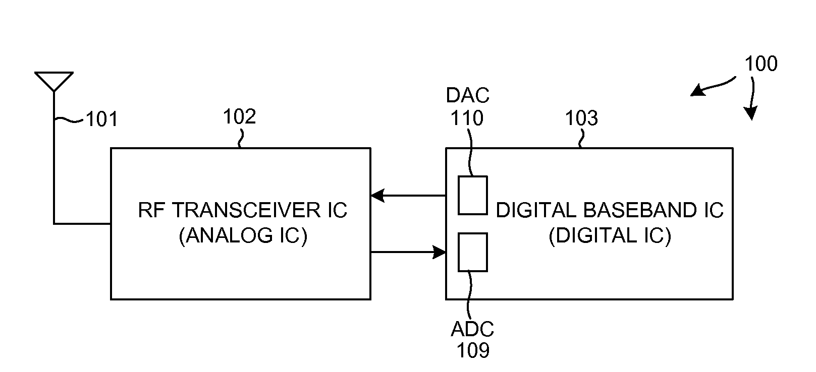
[0025]FIG. 1 is a simplified high level block diagram of an example of a wireless communication device 100. Wireless communication device 100 includes, among other parts not illustrated, an antenna 101, a Radio Frequency (RF) integrated circuit 102, and a digital baseband integrated circuit 103.

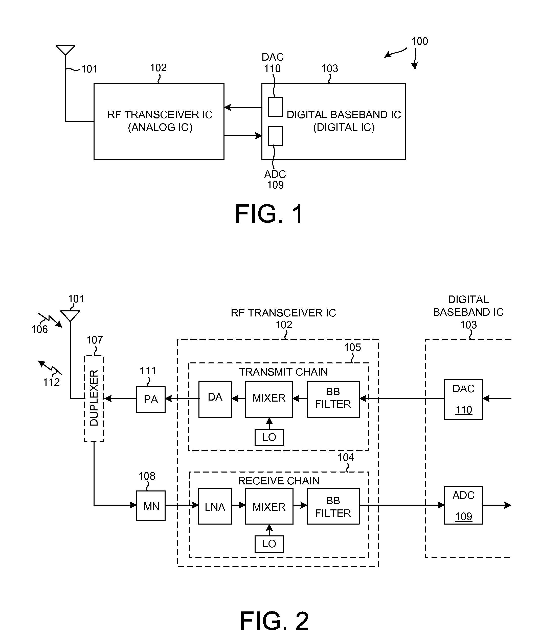
[0026]FIG. 2 is a more detailed block diagram of the antenna 101 and the RF transceiver integrated circuit 102 of FIG. 1. The RF transceiver integrated circuit 102 includes a receive chain 104 and a transmit chain 105. An incoming transmission 106 is received on antenna 101, and passes through a duplexer 107 and a matching network 108 and into the receive chain 104. After being downconverted in frequency in receive chain 104, the received signal passes to an Analog-to-Digital Converter (ADC) 109 in the digital baseband integrated circuit 103. ADC 109 converts the signal into digital samples for further processing. If wireless communication device 100 is to make a transmission, then digital in...


PUM


Abstract

Within a receiver, a channel estimation mechanism involves a hardware interpolator. In a first mode, narrowband pilot values are analyzed to generate channel parameters that are supplied to the interpolator such that the interpolator generates channel estimate values. The channel estimate values are used to demodulate a tile of a frame. In a second mode, broadband pilot values are supplied to an IFFT, thereby generating time domain values. After time domain processing, an FFT is employed to generate intermediate channel estimate values. These intermediate values are analyzed to determine channel parameters, which in turn are supplied to the hardware interpolator so that the interpolator generates a larger number of channel estimate values. After phase adjustment, the channel estimate values are used in demodulation. Use of the interpolator in the broadband mode allows the FFT employed to be of a smaller order, and to consume less power and / or processing resources.

Description

CROSS-REFERENCE TO RELATED APPLICATION[0001]This application claims the benefit under 35 U.S.C. §119 of Provisional Application Ser. No. 61 / 040,449, filed Mar. 28, 2008, said provisional application is incorporated herein by reference.BACKGROUND INFORMATION[0002]1. Technical Field[0003]The present disclosure relates to channel estimation in communication systems.[0004]2. Background Information[0005]In a wireless communication system, a transmitter typically encodes, interleaves, and modulates (i.e., symbol maps) traffic data to obtain data symbols. For a coherent system, the transmitter multiplexes pilot symbols with the data symbols, processes the multiplexed pilot and data symbols to generate a modulated signal, and transmits the signal via a wireless channel. The channel distorts the transmitted signal with a channel response and further degrades the signal with noise and interference. The transmitted signal may reach a receiver via a number of propagation paths. The characterist...

Claims


Application Information

Patent Timeline
Patent Type & Authority Applications(United States)
IPC IPC(8): H04J11/00H04K1/10
CPCH04B1/76H04L25/0212H04L25/023H04J11/00H04L25/0232H04L25/0202
Inventor BUDIANU, PETRU CRISTIANCHAUDHURI, ARUNAVACHALLA, RAGHU N.
Owner QUALCOMM INC
Learn More