


Quick Research
Generate reliable direction feasibility study reports for your R&D in just a few steps.

Technical Q&A
Discover and master advanced knowledge NOW. Basics, ideas, possibilities, all at once.

Find Solutions
As an expert in R&D theories, this can generate solutions to your technical problems instantly.

Evaluate Feasibility
Analyze your overall solution with one click, know your potential R&D risks in advance.

Monitor Landscape
Get weekly tech updates, stay abreast of the latest tech innovations and key insights.
Tape heater and method for manufacturing the same
a technology of tape heaters and tapes, applied in the field of tape heaters, can solve the problems of poor productivity, shortening of the heater, and loss of electrical insulation, and achieve the effects of superior flexibility and stretchability, superior in being easily wrapped around the pipe, and reliably protecting the heater member
- Summary
- Abstract
- Description
- Claims
- Application Information
AI Technical Summary
Benefits of technology
Problems solved by technology
Method used
Image

Examples
first embodiment
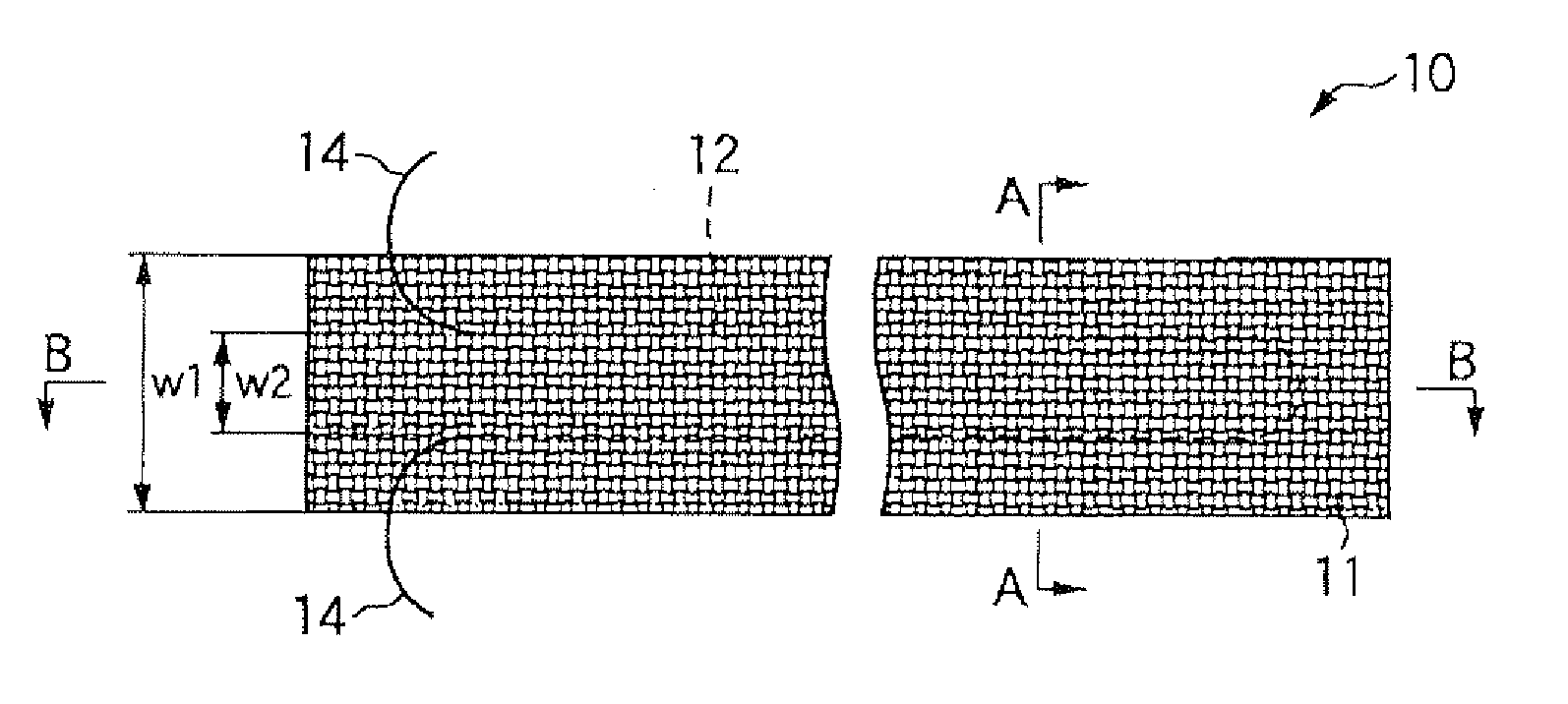
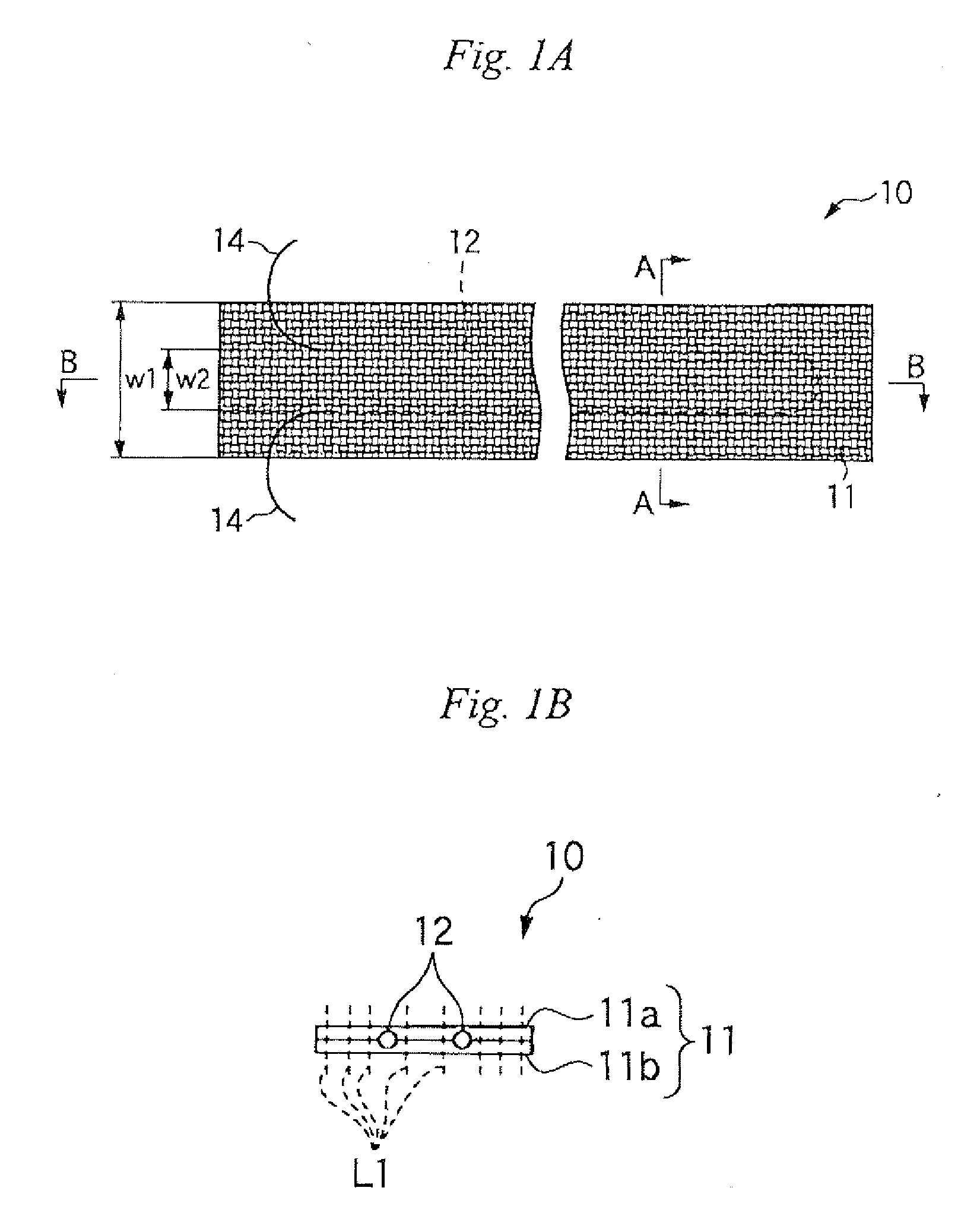
[0052]FIG. 1A is a plan view showing a first embodiment of a tape heater of the present invention, and FIG. 1B is a cross-sectional view taken along line A-A shown in FIG. 1A.
[0053]As illustrated, the tape heater 10 of the present embodiment of the present invention has a fabric base 11 including long lengths of first and second fabric base parts 11a and 11b made of a heat-resistant thread 13 and a heater member 12 sandwiched between the first and second fabric base parts 11a and 11b. Both brims of the first and second fabric base parts 11a and 11b having the heater member 12 sandwiched therebetween and areas between the brims are stitched at predetermined intervals along a longitudinal direction of the tape heater (see reference symbol L1 in FIG. 1B), thereby joining the fabric bases. Contacting of portions of the heater member 12, which would otherwise be caused by movement of the heater member in a widthwise direction, is prevented by stitching. Further, lead wires 14 and 14 to b...
second embodiment
[0063]In the first embodiment, the fabric base 11 is formed from two of the first and second fabric base parts 11a and 11b. As shown in FIG. 5 (a cross section corresponding to FIG. 1B), there is provided a tape heater 10B in which the heater member 12 is sandwiched between the first and second fabric base parts 11a and 11b formed by folding back a single double-width fabric base 11B. In the tape heater 10B, a necessity for sewing up folded portions is obviated.
[0064]In order to manufacture the tape heater 10B, a conventional knitting or weaving machine can be used. For instance, an apparatus 30B schematically shown in FIG. 6 is preferably used. As illustrated, the apparatus 30B has a weaving machine 33 that weaves a single double-width fabric base 11B by supplying the threads 13 from the warp supply units 31 and the weft supply unit 32 (a step of forming a single fabric base). The heater member supply unit 34 that supplies the heater member 12 to an area corresponding to one-half t...
third embodiment
[0066]As shown in FIG. 7 (a cross section corresponding to FIG. 1B), there is provided a tape heater 10C having the heater member 12 sandwiched by a tubular-knitted or tubular-woven fabric base 11C. In the tape heater 10C, a necessity for sewing up both ends of the fabric base 11C is obviated.
[0067]In order to manufacture the tape heater 10C, a conventional knitting or weaving machine can be used. For instance, an apparatus 30C schematically shown in FIG. 8 is preferably used. As illustrated, the apparatus 30C has a tubular weaving machine 37 that weaves a tubular fabric base 11C by supplying the threads 13 from the warp supply units 31 and the weft supply unit 32 (a step of forming a tubular fabric base). The tubular weaving machine 37 is supplied with the heater member 12 from the heater member supply unit 34, and the heater member 12 is disposed inside of the woven tubular fabric base 11C (a step of disposing a heater member inside of a tubular fabric base). The sewing machine 35...
PUM
| Property | Measurement | Unit |
|---|---|---|
| Electrical resistance | aaaaa | aaaaa |
| Flexibility | aaaaa | aaaaa |
| Efficiency | aaaaa | aaaaa |
Abstract
Description
Claims
Application Information
 - R&D Engineer
- R&D Manager
- IP Professional
- Industry Leading Data Capabilities
- Powerful AI technology
- Patent DNA Extraction
Browse by: Latest US Patents, China's latest patents, Technical Efficacy Thesaurus, Application Domain, Technology Topic, Popular Technical Reports.
© 2024 PatSnap. All rights reserved.Legal|Privacy policy|Modern Slavery Act Transparency Statement|Sitemap|About US| Contact US: help@patsnap.com