
Internal egr control device for internal combustion engine

a control device and internal combustion engine technology, applied in the direction of electrical control, process and machine control, instruments, etc., can solve the problem of not being able to properly control the internal egr amount which actually remains in the cylinder

Inactive Publication Date: 2009-09-24
HONDA MOTOR CO LTD
View PDF0 Cites 8 Cited by
  • Summary
  • Abstract
  • Description
  • Claims
  • Application Information

AI Technical Summary

Benefits of technology

[0006]It is an object of the present invention to provide an internal EGR control device for an internal combustion engine, which is capable of properly controlling the internal EGR amount while causing conditions of burned gases to be reflected thereon, in controlling the internal EGR by changing the valve-closing timing of an exhaust valve.
[0009]The volume of burned gases varies with the temperature or pressure of burned gases. Therefore, by correcting the target internal EGR amount according to the temperature and pressure of exhaust gases corresponding to the temperature and pressure of burned gases, it is possible to properly compensate for influence of variation in the volume of burned gases.
[0010]Further, since burned gases include carbon dioxide or moisture vapor which is a triatomic molecule, a gas constant thereof is smaller than that of air which is formed by diatomic molecules, such as oxygen or nitrogen. Further, as the air-fuel ratio is higher, the concentrations of carbon dioxide, moisture vapor and the like become lower, and hence the gas constant of burned gases becomes closer to the gas constant of air, and becomes larger. In view of this, by calculating the gas constant according to the air-fuel ratio parameter, it is possible to properly obtain the gas constant according to the composition of burned gases. From the above, by correcting the target internal EGR amount based on a gas state equation, using the obtained temperature and pressure of exhaust gases, and the gas constant which is determined as above, it is possible to properly set the target internal EGR amount.
[0011]Further, in the present invention, the valve-closing timing of the exhaust valve is calculated according to the target internal EGR amount which is corrected as above, and the variable valve mechanism is controlled based on the valve-closing timing. Therefore, it is possible to properly control the internal EGR amount, while causing the conditions of burned gases to be excellently reflected thereon.

Problems solved by technology

Therefore, in the conventional internal EGR control device, it is not possible to properly control the internal EGR amount which actually remains in the cylinders, depending on the conditions of burned gases.

Method used


Image

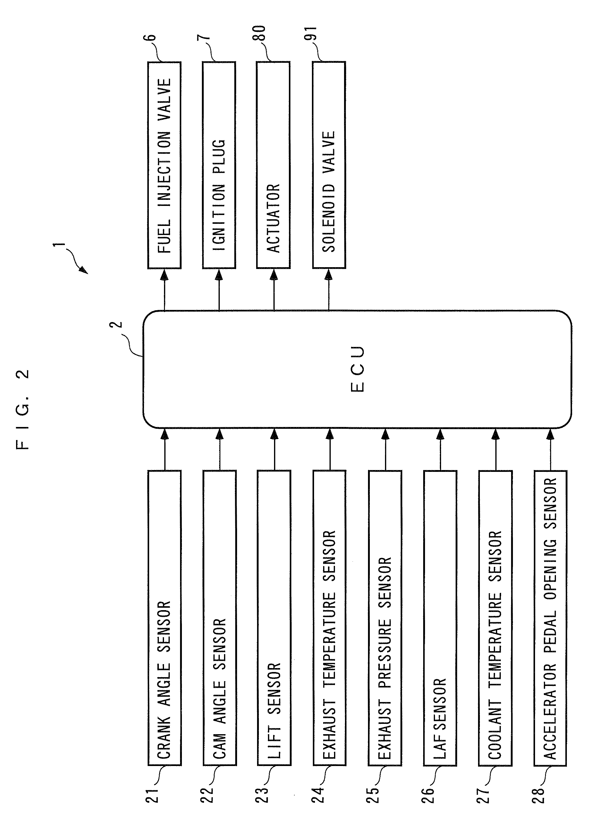
  • Internal egr control device for internal combustion engine
  • Internal egr control device for internal combustion engine
  • Internal egr control device for internal combustion engine

Examples


Embodiment Construction

[0024]The invention will now be described in detail with reference to the drawings showing preferred embodiment thereof.FIG. 1 schematically shows the arrangement of an internal EGR control device 1 according to an embodiment of the present invention and an internal combustion engine 3 (hereinafter simply referred to as the “engine”) to which the present invention is applied. The engine 3 is a gasoline engine that has four cylinders 3a (only one of which is shown), and is installed on a vehicle, not shown.

[0025]The engine 3 has a cylinder head 3c having an intake pipe 4 and an exhaust pipe 5 connected thereto, and a fuel injection valve 6 and an ignition plug 7 (see FIG. 2) mounted therethrough such that they face a combustion chamber 3d (only one of each of which is shown), for each cylinder 3a thereof. The fuel injection valve 6 is of a direct fuel-injection type which is configured to directly inject fuel to the vicinity of the ignition plug 7 in the combustion chamber 3d. The fu...


PUM


Abstract

An internal EGR control device for an internal combustion engine, which is capable of properly controlling an internal EGR amount, while causing conditions of burned gases to be reflected thereon in controlling the internal EGR by changing valve-closing timing of an exhaust valve. An internal EGR control device sets a target internal EGR amount EGRINCMD as a target of the internal EGR amount according to detected operating conditions of an internal combustion engine, and a target internal EGR amount EGRINC is determined by correcting the target internal EGR amount based on a gas state equation, using obtained temperature and pressure of exhaust gases, and a calculated gas constant R. Then, according to the corrected target internal EGR amount EGRINC, the valve-closing timing of an exhaust valve is calculated, and a variable valve mechanism is controlled based on the calculated valve-closing timing of the exhaust valve.

Description

BACKGROUND OF THE INVENTION[0001]1. Field of the Invention[0002]The present invention relates to an internal EGR control device for an internal combustion engine, for controlling internal EGR which causes burned gases to remain in cylinders.[0003]2. Description of the Related Art[0004]Conventionally, there has been proposed an internal EGR control device of this kind in Japanese Laid-Open Patent Publication (Kokai) No. S62-10411. In this internal EGR control device, the amount of internal EGR caused to remain in cylinders is controlled by changing an intake cam phase and an exhaust cam phase with respect to a crankshaft by a variable intake cam phase mechanism and a variable exhaust cam phase mechanism, respectively, and by changing the lift of an intake valve by a variable intake lift mechanism. Specifically, the opening and closing timing of intake and exhaust valves is controlled by controlling the above-mentioned intake / variable exhaust cam phase mechanism and the variable intak...

Claims


Application Information

Patent Timeline
IPC IPC(8): F02D41/00
CPCF02D13/0246F02D13/0265F02D41/006F02D41/1446Y02T10/18F02D41/3035F02D2041/001Y02T10/47F02D41/1448Y02T10/12Y02T10/40
Inventor ITOGA, CHIHOOGAWA, KENKITAMURA, TORU
Owner HONDA MOTOR CO LTD
Learn More