
Light source module and vehicular lamp

a technology of light source module and vehicular lamp, which is applied in the direction of light source semiconductor devices, fixed installations, lighting and heating apparatus, etc., can solve the problems of difficult to achieve sufficient heat radiation performance, and difficult to secure a sufficient amount of emitted light luminous flux to increase brightness, so as to improve safety and traveling performance, improve external visibility, and increase the brightness of vehicular lamps

Active Publication Date: 2009-09-24
KOITO MFG CO LTD
View PDF7 Cites 15 Cited by
  • Summary
  • Abstract
  • Description
  • Claims
  • Application Information

AI Technical Summary

Benefits of technology

[0008]However, a sufficient amount of luminous flux must be secured from light emitted from the light source to increase the brightness of vehicular lamps, both from the standpoint of headlamps or the like to improve safety and traveling performance during vehicle running, and from the standpoint of marker lamps or the like to improve external visibility and so forth.
[0009]Such increased brightness is accomplished in the above-mentioned light source module by improving the heat radiation performance in order to suppress a temperature increase caused by heat generated while the light source is driving, and also by increasing the power supplied to the light source (a large power supply).

Problems solved by technology

Therefore, it is difficult to achieve sufficient heat radiation performance and, because the amount of power supplied to the semiconductor light emitting element is small, it is difficult to secure a sufficient amount of luminous flux from emitted light to increase brightness.

Method used


Image

  • Light source module and vehicular lamp
  • Light source module and vehicular lamp
  • Light source module and vehicular lamp

Examples


Embodiment Construction

[0033]Hereinafter, embodiments of a light source module and a vehicular headlamp of the present invention will be described with reference to the accompanying drawings.

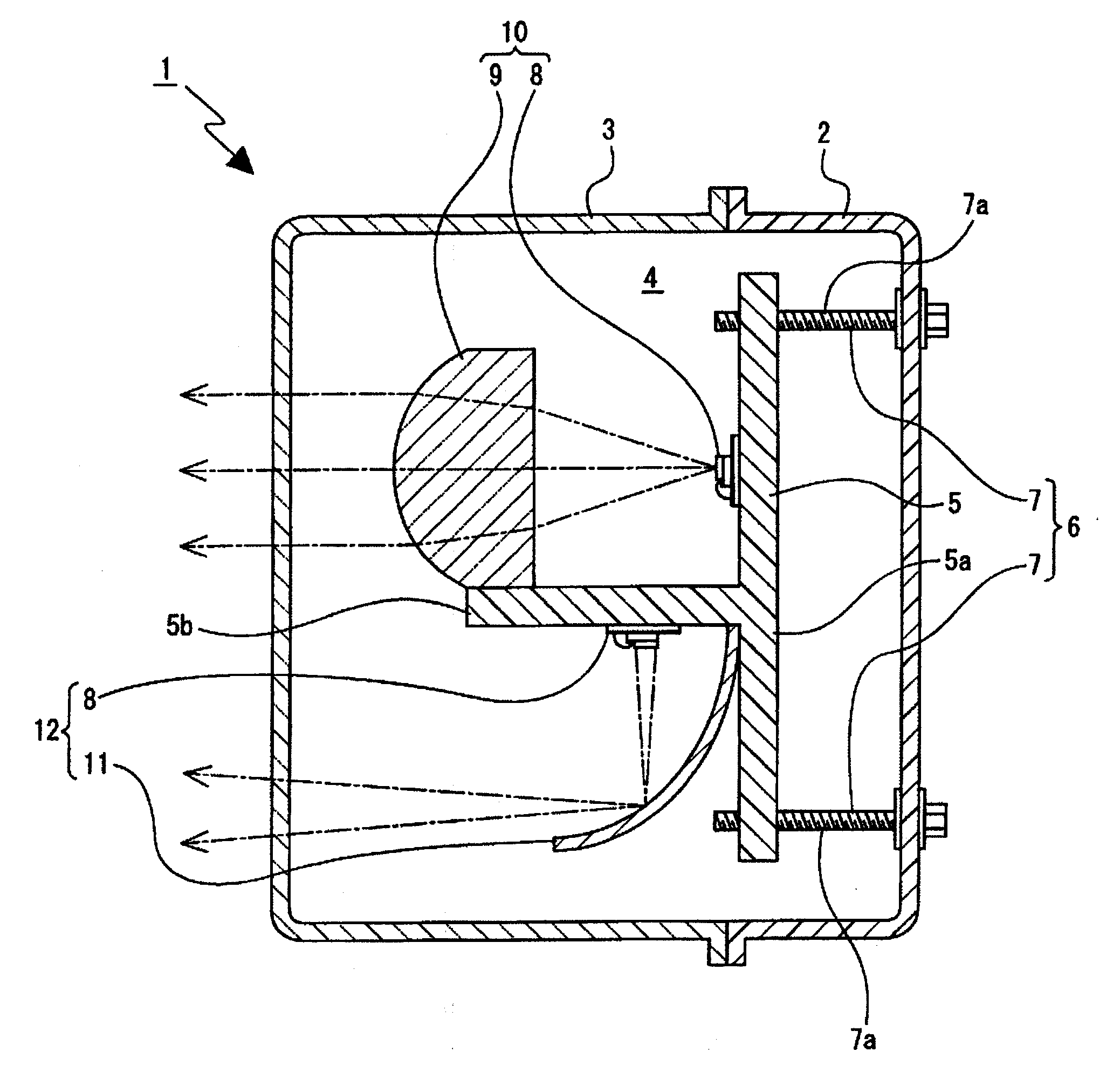
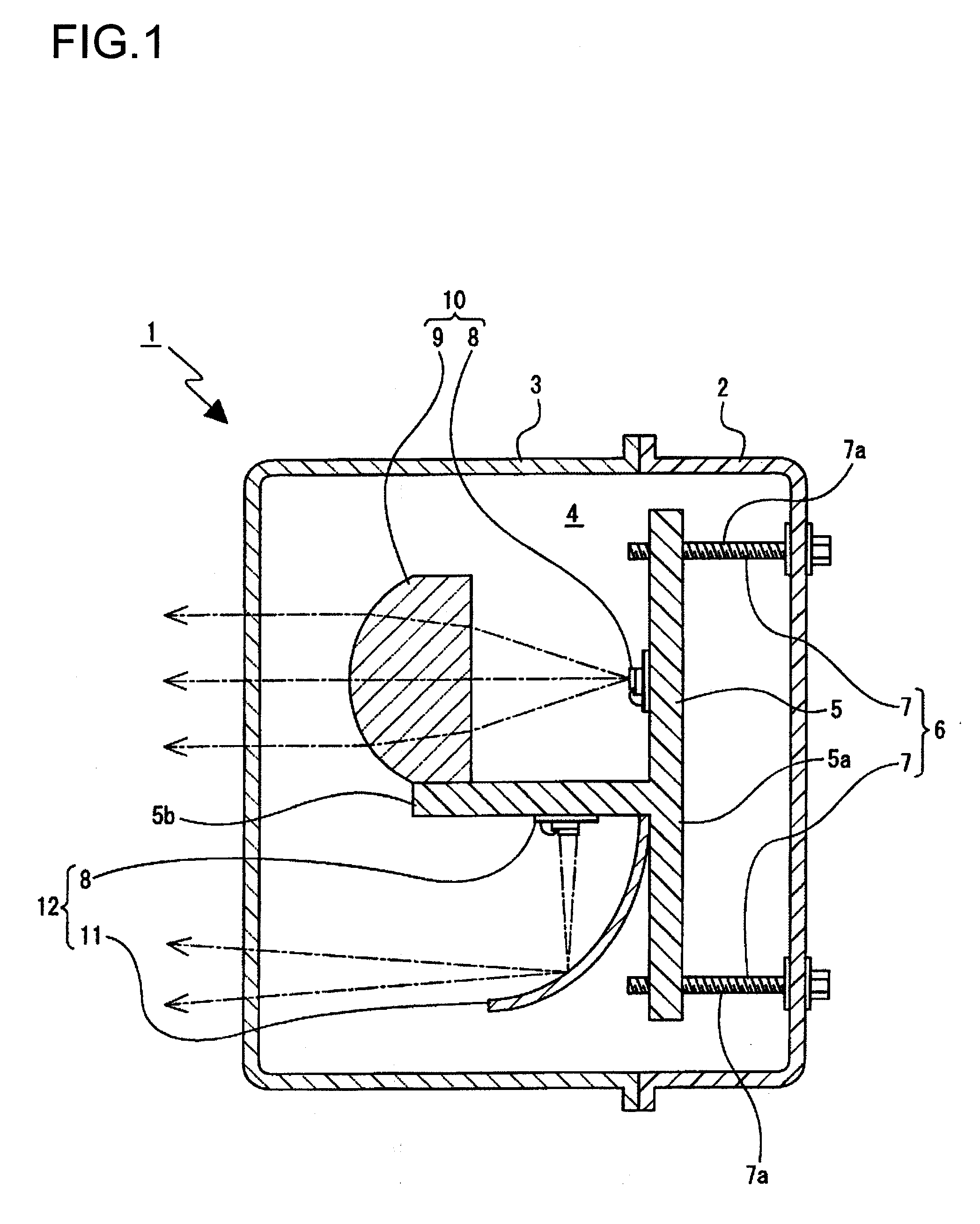
[0034]A vehicular lamp 1 is, for example, a vehicular headlamp. As FIG. 1 illustrates, the vehicular lamp 1 is formed by a container-like lamp housing 2 that opens forward, a cover 3 that covers the opening of the lamp housing 2, and a lamp space 4 defined by the lamp housing 2 and the cover 3 with necessary components arranged therein.

[0035]A bracket 5 is disposed in the lamp space 4 via an optical axis adjustment mechanism 6. The bracket 5 includes a vertically extending base portion 5a and an attachment projection portion 5b that protrudes from the base portion 5a.

[0036]The optical axis adjustment mechanism 6 is, for example, an aiming adjustment mechanism. The optical axis adjustment mechanism 6 includes aiming screws 7, 7 that are vertically separated from one another and are each rotatably supported on the lamp...


PUM


Abstract

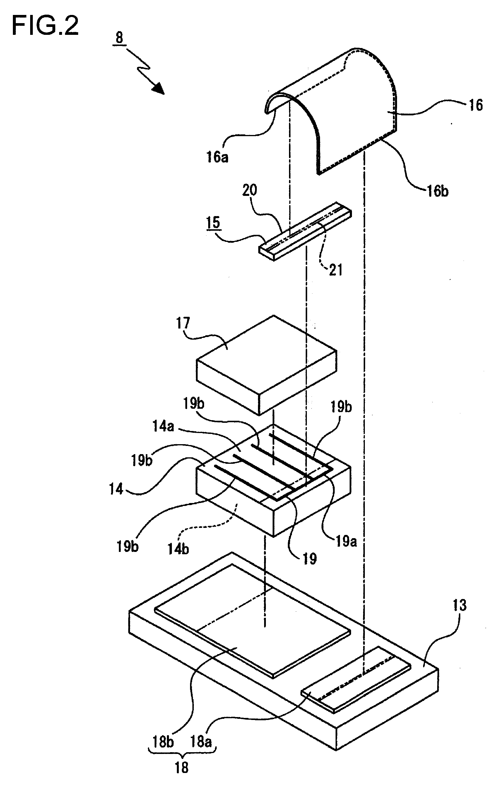
A light source module includes a circuit board on which a circuit pattern is formed; a semiconductor light emitting element; an electrode pad; and a connecting body. The semiconductor light emitting element includes a first surface formed into an oblong shape, and a second surface positioned facing opposite the first surface. The second surface is connected with a second part of the circuit pattern. The electrode pad is provided on the first surface of the semiconductor light emitting element and includes a connecting portion. The connecting body is connected with the connecting portion of the electrode pad and a first part of the circuit pattern. The electrode pad is provided on a portion of the semiconductor light emitting element that includes one end portion of the first surface. The connecting portion of the electrode pad is provided at a position in one of a continuous and spaced manner in the lengthwise direction of the electrode pad.

Description

BACKGROUND OF INVENTION[0001]1. Field of the Invention[0002]The present invention relates to a light source module and a vehicular headlamp. More specifically, the present invention relates to increasing brightness by connecting a connecting body with an electrode pad provided on an end portion of a semiconductor light emitting element.[0003]2. Related Art[0004]A light source module exists that uses a semiconductor light emitting element such as a light emitting diode (LED) as a light source. Such a light source module is provided in a vehicular lamp that radiates light emitted from the light source as illumination light.[0005]One face of the semiconductor light emitting element is provided with an electrode pad that is connected with a circuit pattern formed on a circuit board.[0006]In past light source modules in vehicular lamps, the electrode pad provided on one face of the semiconductor light emitting element is connected with the circuit pattern by one wire (see Patent Document...

Claims


Application Information

Patent Timeline
Patent Type & Authority Applications(United States)
IPC IPC(8): F21S6/00H01L33/00F21S8/10F21V19/00F21Y101/02H01L33/48H01L33/50H01L33/58H01L33/60H01L33/62H01L33/64
CPCF21K9/00F21S48/1154F21S48/1159F21Y2101/02H01L25/0753H01L2924/12041H01L24/34H01L2924/00H01L2224/40225H01L24/40H01L2224/40091F21Y2115/10H01L2224/371H01L2224/84801H01L24/37F21S41/143F21S41/148F21S41/151H01L24/84H01L2924/00014
Inventor TSUTSUMI, YASUAKI
Owner KOITO MFG CO LTD
Learn More