
Syringe mold

a technology of syringe and mold, which is applied in the field of syringe mold, can solve the problems of failure of mold, limited outer diameter of flow passage, and inability to obtain sufficient circulating flow, and achieve the effect of sufficient cooling flow

Inactive Publication Date: 2009-09-17
DAIKYO SEIKO LTD
View PDF12 Cites 8 Cited by
  • Summary
  • Abstract
  • Description
  • Claims
  • Application Information

AI Technical Summary

Benefits of technology

[0024]In a syringe mold according to the present invention, the coolant flow can be sufficient by positioning the coolant circulation outward and the coolant circulation homeward close to the cavity space and setting the cross-sectional area of the coo

Problems solved by technology

There is a molding failure problem due to insufficient cooling of the molding male die (core cylinder) in the conventional mold because it has the cam mechanism for coupling the cam axis to the slide core and the cam mechanism is an obstacle for cooling.
The outer diameter of the flow passage is limited and a sufficient circulating flow cannot be obtained.

Method used


Image

  • Syringe mold
  • Syringe mold
  • Syringe mold

Examples


Embodiment Construction

[0025]A syringe mold according to the best mode of the present invention will be described referring to drawings. Same reference numerals will be given to the identical or similar elements and the duplicative explanation will be omitted.

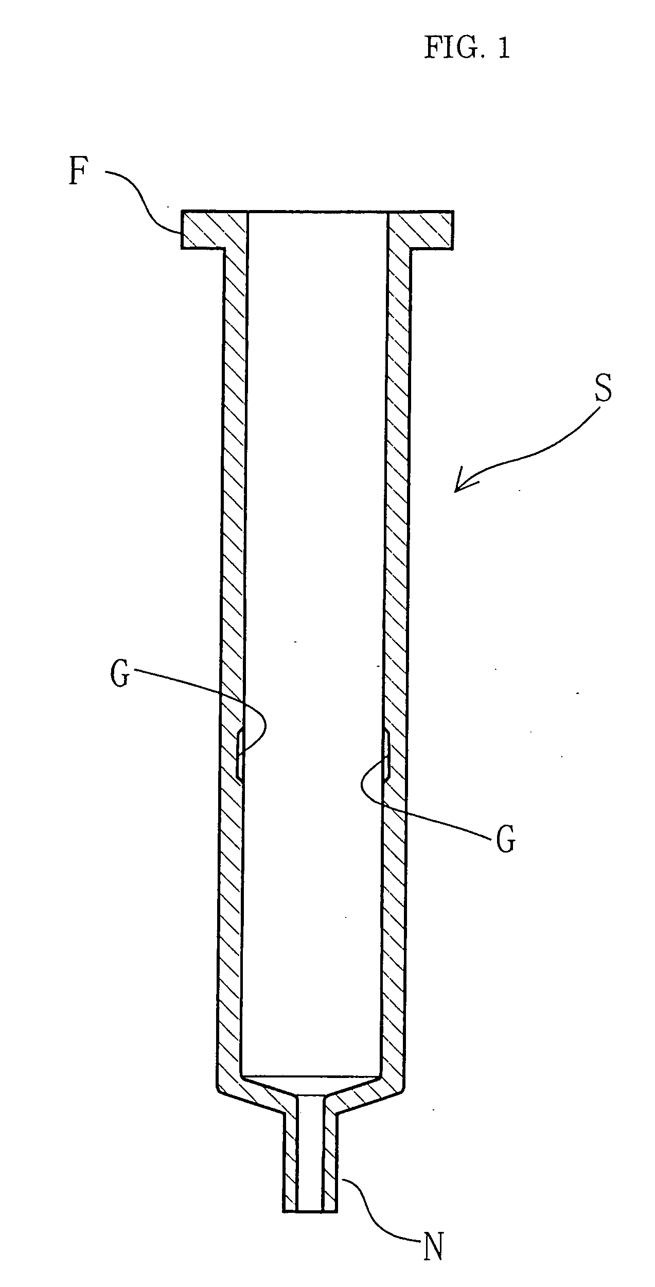
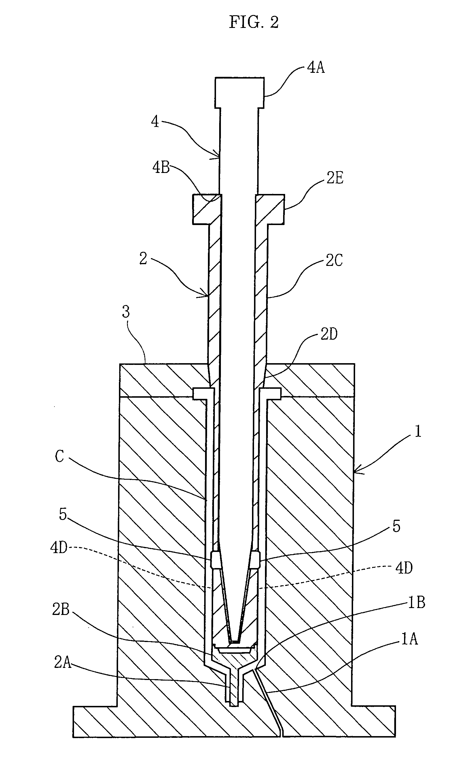
[0026]FIG. 1 shows a longitudinal cross-sectional view of a syringe which is injection-molded by the syringe mold according to one embodiment of the present invention. FIG. 2 shows a cross-sectional view of a syringe mold shown in FIG. 1. One embodiment of a syringe mold according to the present invention is a syringe mold for injection-molding the syringe S for mixing two medical agents shown in FIG. 1, that is to say, the syringe S has a flange portion F at the base portion, a nozzle portion N at the tip portion and a communicating groove G for mixing two medical agents formed on the inner circumference.

[0027]As shown in FIG. 2, the syringe mold comprises a female die 1 for forming the outer circumference including a nozzle part N of the syringe S,...


PUM

PropertyMeasurementUnit
Circumferenceaaaaaaaaaa

Abstract

A syringe mold with a coolant circulation outward and homeward positioned close to the cavity space and a sufficient coolant circulating flow for cooling a core cylinder is provided.Slide cores (5, 5) are put in the position where the slide cores (5, 5) protrude from the circumference of the core cylinder (2) by moving the slide core operating jig (4) forward in the axial direction of the core cylinder (2) while cooling the core cylinder (2) by the coolant. Then, a two medical agent mixing type syringe having a communicating groove on the inner circumference for mixing two medical agents is injection-molded. A molding failure due to insufficient cooling of the core cylinder (2) can be prevented by positioning the coolant outward and homeward close to the cavity space and making the cross sectional area of the coolant outward and homeward enough large because the coolant outward and homeward is partitioned by the circumference of the jig container space in the core cylinder (2).

Description

TECHNICAL FIELD[0001]The present invention relates to a syringe mold for injection-molding a two medical agent mixing type syringe.BACKGROUND ART[0002]A communicating groove is injection-molded in an integrated manner on the inner circumference of a two medical agent mixing type syringe for mixing two medical agents contained on the both sides of a piston by circumventing the piston. A conventional syringe mold for a two medical agent mixing type syringe with such a communicating groove formed on the inner circumference is disclosed in Japanese Patent Laid-open Application No. H8-132444.[0003]The syringe mold disclosed in Japanese Patent Laid-open Application No. H8-132444 comprises a cylindrical male die (core cylinder) for molding the inner circumference of the syringe, a slide core for molding the communicating groove which is mounted to move in and out the circumference of the molding male die (core cylinder), and a rotational axis rod incorporated in the molding male die (core ...

Claims


Application Information

Patent Timeline
IPC IPC(8): B29C45/56
CPCA61M5/284Y10S425/01B29L2031/7544B29C45/7312B29C45/4421
Inventor TOGASHI, HIROSHISUDO, MORIHIRO
Owner DAIKYO SEIKO LTD
Learn More