
Directionless optical architecture and highly available network and photonic resilience methods

a network and optical architecture technology, applied in the field of optical networks, can solve the problems of unfavorable network connectivity, unfavorable network connectivity, and the cost of 40 g or 100 g interfaces required to support core router connections is not as cost-effective, and achieves superior resiliency, reduced deployment costs, and increased resiliency

Active Publication Date: 2009-09-17
CIENA
View PDF60 Cites 57 Cited by
  • Summary
  • Abstract
  • Description
  • Claims
  • Application Information

AI Technical Summary

Benefits of technology

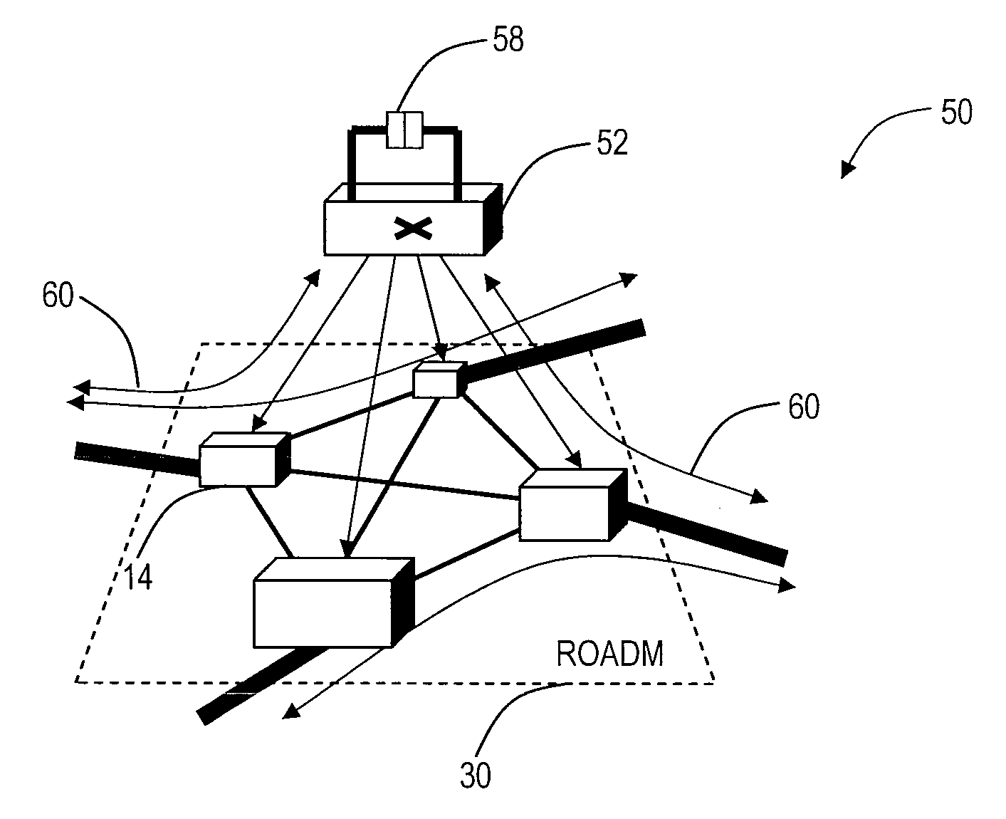
[0026]In various exemplary embodiments, the present invention provides a directionless (i.e., a direction-independent) optical architecture for reconfigurable optical add / drop multiplexers (ROADMs) and wavelength selective switches (WSSs). The directionless architecture utilizes a wavelength switch coupled between client devices and ROADMs / WSSs to eliminate the need to hard-wire client devices to a wavelength division multiplexed (WDM) network. Accordingly, client device connections can be automatically routed without manual intervention to provide a highly resilient network design which can recover route diversity during failure scenarios. Additionally, the present invention minimizes deployments of costly optical transceivers while providing superior resiliency. Further, the present invention couples the directionless optical architecture and associated optical protection mechanisms with existing mesh restoration schemes to provide additional resiliency. Here, the present invention provides mesh restoration, such as through SONET / SDH, across a G.709 / OTN enabled sequence of rings. The G.709 rings provide high availability connectivity for the SONET / SDH connections.

Problems solved by technology

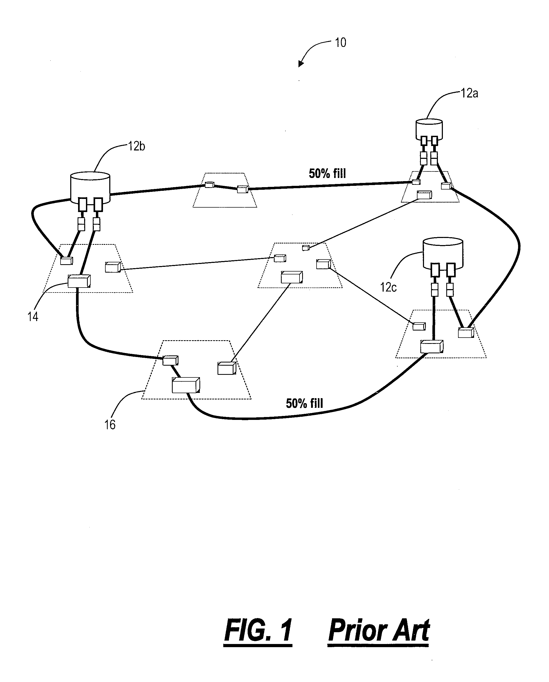
While the architecture of the network 10 is reasonably efficient from a capital equipment (“CAPEX”) perspective, it raises some challenges that can impact the operating expenses (“OPEX”) required to operate and maintain this network 10.
Another challenge is associated with the coordination of network maintenance activities between operations personnel who are responsible for the IP network, i.e. routers 12, and those responsible for the underlying transport connections, i.e. WSSs 14.
Without careful cooperation between operations personnel, it is possible that simultaneous maintenance could occur on links between routers 12a to 12b (by transport) and between routers 12a to 12c (by IP) causing unnecessary network disruption.
However, there is concern that the cost of 40 G or 100 G interfaces required to support core router connections is not as cost effective as 10 G and therefore should be minimized throughout the transmission path, i.e. OXCs would require additional 40 G or 100 G interfaces.
Furthermore, dedicating 40 G or 100 G modules on an OXC to aggregate flows of data is wasteful of precious backplane and switch capacity.
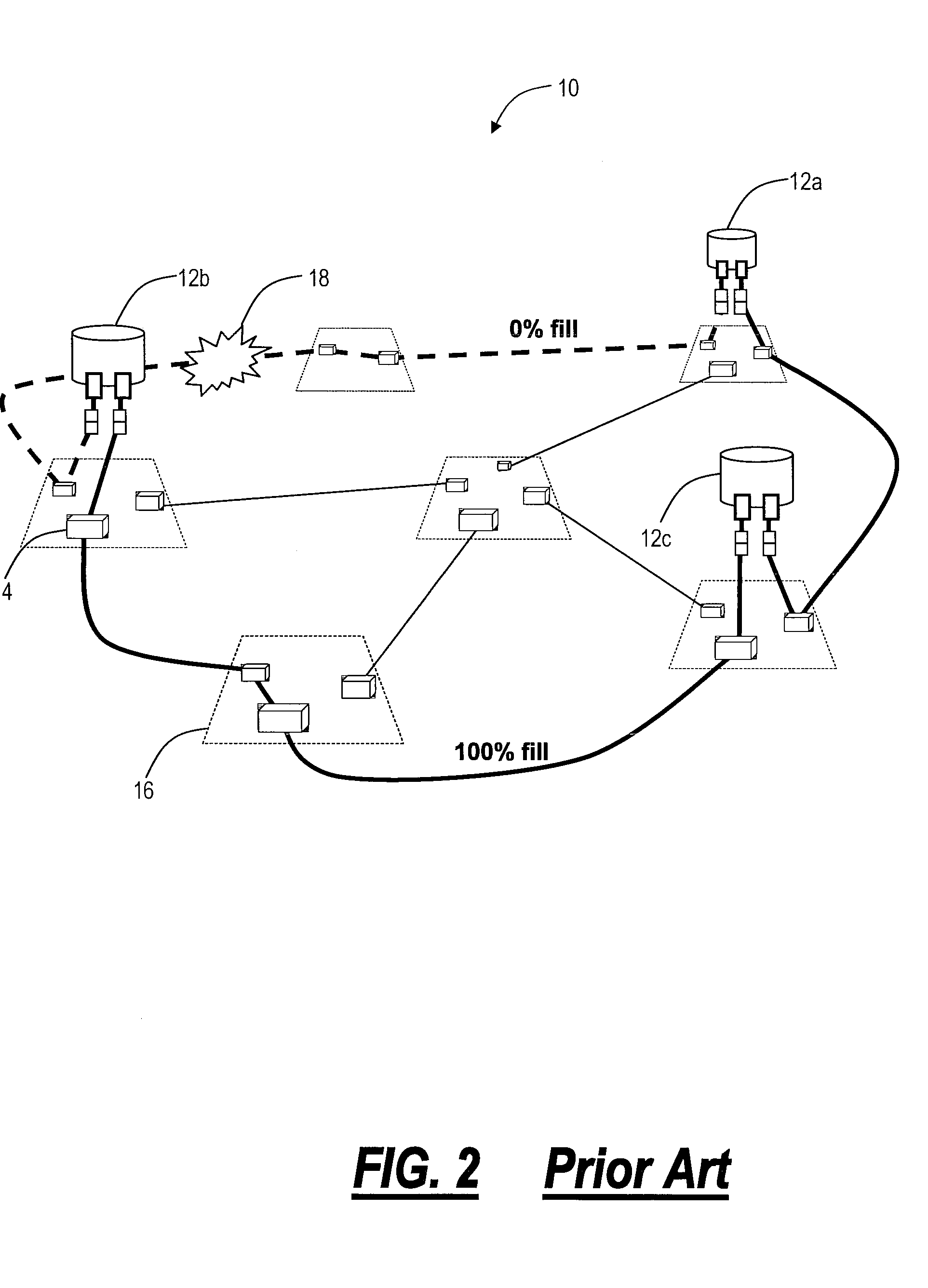
However, because of the static nature of the optical connectivity, it is not possible to reconfigure the optical layer so as to restore diverse links between the end nodes.
For some carriers this is a significant issue.
Therefore, while the pass-through traffic of today's ROADM 30 is highly flexible, the static connectivity of the add / drop traffic limits the flexibility of the end-to-end solution.
However, because the add / drop function is dedicated on a per-direction basis, the solution with ROADM 30 is no more capable of re-establishing a second backup connection as the static network above.
As network grows, there may be lots of stranded ports, and wavelengths cannot be dynamically re-optimized to reduce blocking probability.
Further, connections to the receivers 44 cannot be automatically altered due to the hard-wire connections 42 preventing rerouting to restore route diversity during failures.
One of the major challenges facing a number of network operators today is a high incidence of fiber cuts occurring randomly in the network.
Such failures are a common occurrence in developing nations such as India where significant new infrastructure building is taking place (resulting in lots of digging up of fiber cables).
Because most of these carriers are currently using ring protection methods to protect service, their networks are only able to accommodate one fiber failure on a single ring at any one time.
High fiber failure probability therefore leads to the isolation of network elements when two cuts occur simultaneously on the same ring and therefore results in a degradation of end-to end service.
This helps increase service availability but, in many cases, does not allow the carriers to meet their target availability objective (particularly for high value e.g. banking clients who demand ‘always on’ service).
A challenge with both ring protection and mesh restoration is the fact that fiber failures are statistically dependent upon the distance between the switching nodes in the network.
So, even if mesh restoration is used, if the distance between mesh restoration switch sites is too long, then there still exists an increased probability that a service node can be isolated due to simultaneous failures on each of the (multiple) links connected to that node .
. . thus losing service.
Unfortunately, while perhaps possible, the interaction of SDH / SONET between different vendor's equipment for ring protection is highly complicated and not advised.
Consequently, it does not make engineering or operational sense to operate SDH / SONET rings between mesh restoration nodes belonging to one vendor and SDH / SONET rings belonging to a second vendor.
This has been shown to be operationally challenging to engineer.
Also, in some network designs, it may not be cost effective (or prudent from a traffic management perspective) to put a large cross-connect with mesh restoration capabilities at every node in the network.

Method used


Image

  • Directionless optical architecture and highly available network and photonic resilience methods
  • Directionless optical architecture and highly available network and photonic resilience methods
  • Directionless optical architecture and highly available network and photonic resilience methods

Examples


Embodiment Construction

[0054]In various exemplary embodiments, the present invention provides a directionless optical architecture for reconfigurable optical add / drop multiplexers (ROADMs) and wavelength selective switches (WSSs). The directionless architecture utilizes a directionless wavelength switch coupled between client devices and ROADMs / WSSs to eliminate the need to hard-wire client devices to a wavelength division multiplexed (WDM) network. Accordingly, client device connections can be automatically routed without manual intervention to provide a highly resilient network design which can recover route diversity during failure scenarios. Additionally, the present invention minimizes deployments of costly optical transceivers while providing superior resiliency. Further, the present invention couples the directionless optical architecture and associated optical protection mechanisms with existing mesh restoration schemes to provide additional resiliency. Here, the present invention provides mesh re...


PUM


Abstract

The present invention provides a directionless optical architecture for reconfigurable optical add / drop multiplexers (ROADMs) and wavelength selective switches (WSSs). The directionless architecture utilizes a directionless wavelength switch coupled between client devices and ROADMs / WSSs to eliminate the need to hard-wire client devices to a wavelength division multiplexed (WDM) network. Accordingly, client device connections can be automatically routed without manual intervention to provide a highly resilient network design which can recover route diversity during failure scenarios. Additionally, the present invention minimizes deployments of costly optical transceivers while providing superior resiliency. Further, the present invention couples the directionless optical architecture and associated optical protection mechanisms with existing mesh restoration schemes to provide additional resiliency.

Description

FIELD OF THE INVENTION[0001]The present invention relates generally to optical networks. More particularly, the present invention provides a directionless optical architecture for reconfigurable optical add / drop multiplexers (ROADMs) and wavelength selective switches (WSSs) which can be utilized to provide highly available network, photonic resiliency, and wavelength optimization.BACKGROUND OF THE INVENTION[0002]As point-to-point Internet Protocol (IP) flows increase in bandwidth, core router connections are being driven to higher capacities. Today, core router interfaces are starting to move from 10 Gbps to 40 Gbps while 100 Gbps connections are already in the planning stage. With this increase in capacity comes a heightened responsibility to maintain high availability service by minimizing the time that these very expensive, high bandwidth connections are out of service due to failure events or scheduled maintenance activities.[0003]Referring to FIGS. 1 and 2, a network 10 illustr...

Claims


Application Information

Patent Timeline
IPC IPC(8): H04J14/00
CPCH04J14/0206H04Q2011/0047H04J14/0212H04J14/0213H04J14/0217H04J14/0227H04J14/0284H04J14/029H04J14/0291H04J14/0294H04J14/0295H04Q11/0062H04Q2011/0081H04J14/0246H04J14/025H04Q11/0005H04J14/0209H04J14/02122
Inventor BLAIR, LOUDONFRANKEL, MICHAEL Y.
Owner CIENA
Learn More