Sealing device for bearing

a sealing device and bearing technology, applied in the direction of engine sealing, bearing components, shafts and bearings, etc., can solve the problems of reducing the output of the bearing due to the size reduction, components needing to bear high temperature, and the operating conditions of the automobile have tended to become more severe, so as to achieve the effect of reducing the running torque and high sealing properties

Active Publication Date: 2009-09-10
JTEKT CORP
View PDF6 Cites 21 Cited by
  • Summary
  • Abstract
  • Description
  • Claims
  • Application Information

AI Technical Summary

Benefits of technology

[0009]An object of the invention is to provide a sealing device for a bearing, which can appropriately self-control the sealing property of the bearing according to the rotation speed thereof and can achieve both of higher sealing property at low-speed rotation and lower running torque at high-speed rotation.

Problems solved by technology

However, a reduction in an output thereof due to the size reduction is inevitable.
Consequently, these components need to bear high temperature.
In recent years, operating conditions of automobiles have tended to become more severe.
(1) A sub-seal lip is added to the apparatus in addition to a main seal lip. Thus, frictional sliding parts between the inner and outer rings are increased. Consequently, bearing torque is increased. Accordingly, there is a fear that this may be a hindrance to high-speed rotation performance. More particularly, when an axially exposed thread of the sub-seal lip is increased to enhance the waterproofing property, the sliding friction of the seal lip is further increased. Thus, the problem of increase in torque becomes marked.
(2) In the apparatus disclosed in JP-A-2005-282669, a distal end surface of the sub-seal lip is formed to be flat. The sub-seal lip is slide-contacted with the slinger on the distal surface thereof by being radially outwardly inclined. According to such a structure, when the sub-seal lip is elastically deformed by a centrifugal force due to the rotation of the outer ring, the distal end surface thereof is easily floated up from the slinger. Even in a relatively low speed rotation state, the sealing ability of the apparatus is easily deteriorated. More specifically, in a case where a vehicle runs while being submerged in a river, even when the running speed of the vehicle is low, the sealing property of the sub-seal lip is easily impaired. This is likely to lead to a disadvantage that water filled around the bearing rapidly infiltrates thereinto.

Method used


Image

  • Sealing device for bearing
  • Sealing device for bearing
  • Sealing device for bearing

Examples


first embodiment

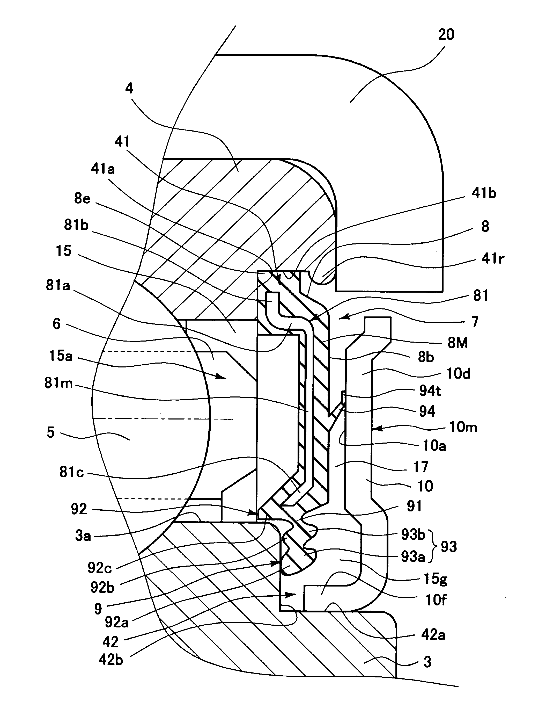
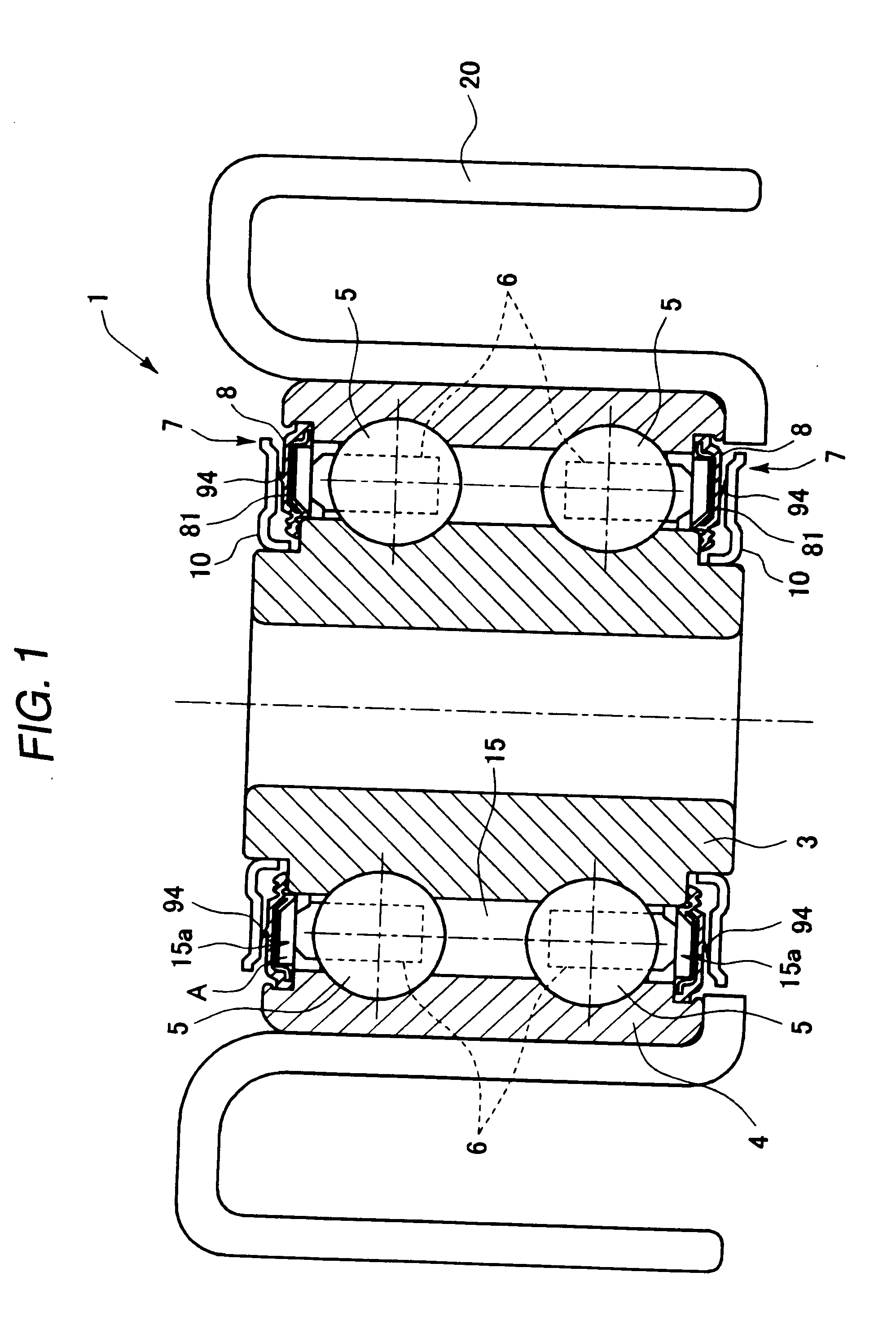
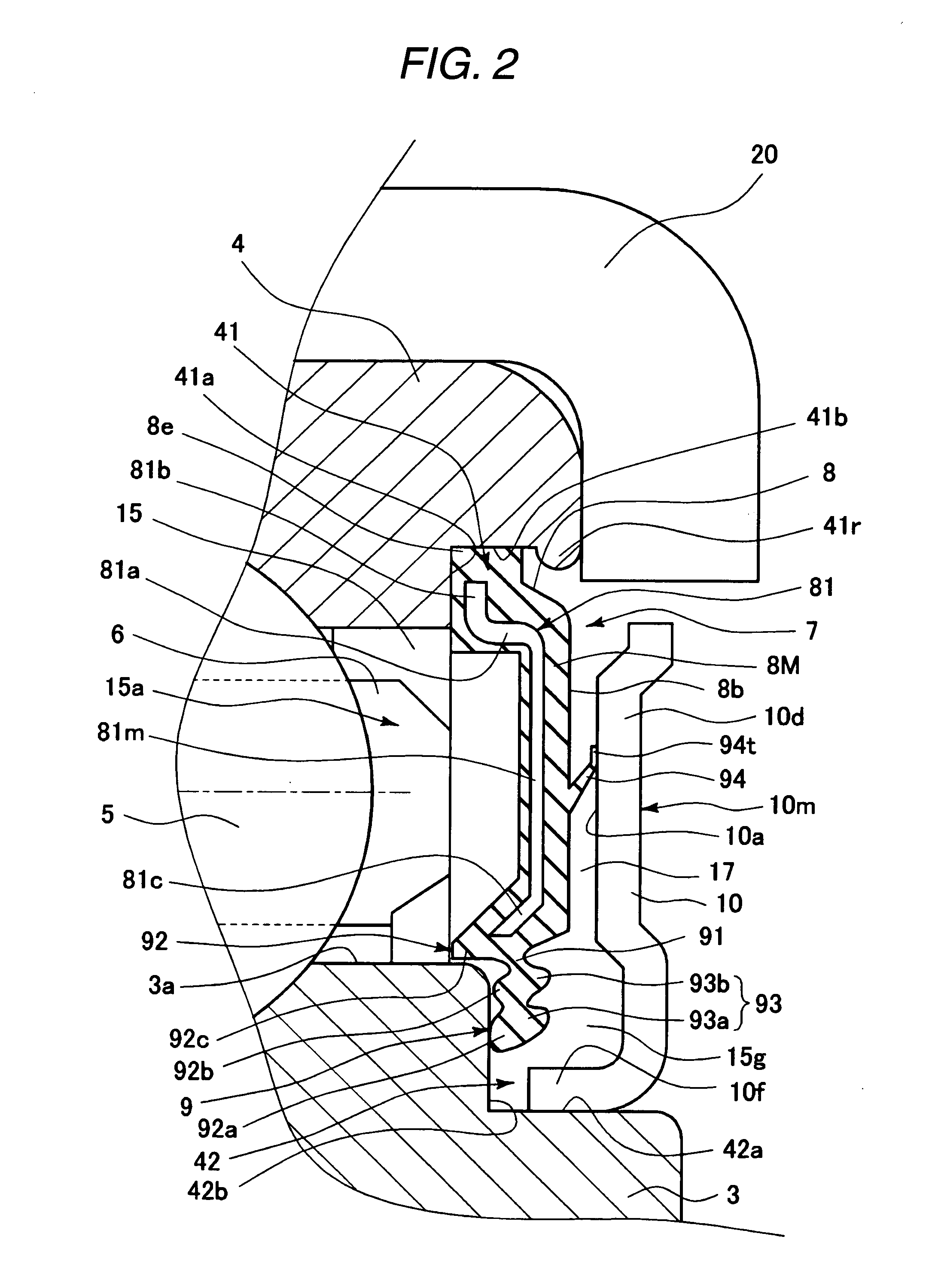
[0074]Hereinafter, embodiments of the invention are described with reference to the accompanying drawings. FIG. 1 is a cross-sectional view illustrating an embodiment of a bearing for an idler pulley, to which a sealing device for a bearing according to a first embodiment of the invention is applied. A bearing 1 is used for rotationally supporting an idler pulley for an automobile. The bearing 1 is formed to be a double row deep groove ball bearing (radial bearing) to be used such that an inner ring 3 is provided at a non-rotating side, and that an outer ring 4 is provided at a rotating side. Balls 5 serving as rolling elements are arranged in a rolling element arranging space 15 formed between the inner ring 3 and the outer ring 4 while the circumferential arrangement integrals thereof are regulated by retainers 6 at the respective rows. A pulley 20 is concentrically fit onto the outer circumferential surface of the outer ring 4.

[0075]In the bearing 1, sealing devices 7 are provide...

second embodiment

[0094]Next, a second embodiment of the invention is described below with reference to FIGS. 13 to 17. The second embodiment differs from the first embodiment mainly in the configuration of the sub-seal lip. Thus, the following description centers on the configuration of the sub-seal lip. Each component common to the first and second embodiments is designated with the same reference numeral. The description of such components is omitted.

[0095]FIG. 13 is an enlarged cross-sectional view illustrating a sealing device portion for a bearing according to a second embodiment of the invention. FIG. 14 is an enlarged cross-sectional view illustrating a sub-seal lip of the sealing device for a bearing illustrating in FIG. 13.

[0096]As illustrated in FIG. 15, an annular branch seal lip 95 is formed at a radially midway position on the inner circumferential surface of the sub-seal lip 94 so as to protrude toward the inner surface of the slinger 10. In a case where the outer ring 4 is in a non-ro...

third embodiment

[0105]Next, a third embodiment of the invention is described below with reference to FIGS. 18 to 22. The third embodiment differs from the first embodiment mainly in the configuration of each of the sub-seal lip and the slinger. Thus, the following description centers on the configuration of the sub-seal lip and the slinger. Each component common to the first and third embodiments is designated with the same reference numeral. The description of such components is omitted.

[0106]As illustrated in FIG. 18, a conical sub-seal lip 94, whose diameter is increased toward the outer side of the bearing in a state, in which the sliding seal portion 8 is not mounted in the rolling bearing 1, as indicated by imaginary lines in FIG. 18, is formed at a radially central portion of the axial base surface 8b of the sliding seal portion 8, which faces the slinger 10, at the outer side of the bearing. Further, in a state in which the sliding seal portion 8 is mounted in the rolling bearing 1, the dis...


PUM


Abstract

In a sealing device for a bearing, a sub-seal lip is configured such that a slide contact surface is formed like an annular band. As the rotation speed of the bearing increases, the width of the slide contact surface is reduced by a centrifugal force. Thus, sliding friction can effectively be minimized. The torque of the bearing can be prevented from increasing at high-speed rotation. Even when the centrifugal force increases somewhat, only reduction in the width of the slide contact surface is caused. Thus, a slide-contacted state can be maintained. Consequently, the problem of floating-up of the sub-seal lip from a slinger is difficult to occur.

Description

BACKGROUND OF THE INVENTION[0001]This invention relates to a sealing device for a bearing.[0002]Demands for size and weight reduction and interior space expansion of each automobile have forced automobiles to reduce the space of each engine room thereof. The size and weight reduction of electrical components and engine accessories have been more advanced. An electromagnetic clutch, a compressor, and an idler pulley for a car air-conditioner are not exceptions. However, a reduction in an output thereof due to the size reduction is inevitable. The reduction of the output of the electromagnetic clutch is compensated by acceleration thereof. Thus, the idler pulley is accelerated. Further, demands for enhancing quietness promote the sealing of the engine room and accelerate the raising of the temperature in the engine room. Consequently, these components need to bear high temperature. In addition, these components are often attached to a lower portion of the engine room. Accordingly, whi...

Claims


Application Information

Patent Timeline
Patent Type & Authority Applications(United States)
IPC IPC(8): F16C33/76
CPCF16C33/7853F16C33/7859F16J15/164F16C2361/63F16J15/3456F16C19/08F16J15/3256
Inventor NAKAGAWA, YOSHITAKANUMADA, YOUICHITADUMI, HAJIMEOKUMURA, TSUYOSHIYAMAGUCHI, KUNIHIROITO, IKUO
Owner JTEKT CORP
Why Eureka
Try Eureka