
Surgical Bending Forceps and Bending Forceps System

a technology of bending forceps and surgical bending, applied in the field of bending forceps, can solve the problems of destabilising the position of the bone plate to be bent, the swivelling movement of the bending punch can only be limited, and the bending punch can be deflected only to a limited extent, so as to achieve the effect of simplifying handling and manipulation

Active Publication Date: 2009-09-03
STRYKER EURO OPERATIONS HLDG LLC
View PDF13 Cites 28 Cited by
  • Summary
  • Abstract
  • Description
  • Claims
  • Application Information

AI Technical Summary

Benefits of technology

[0015]The first counter bearings or the first bending punch or all these components can be contoured so as to co-operate with a complementary contour of the surgical element. Such a measure has a positionally stabilising effect with regard to the surgical element and accordingly facilitates the bending procedure.
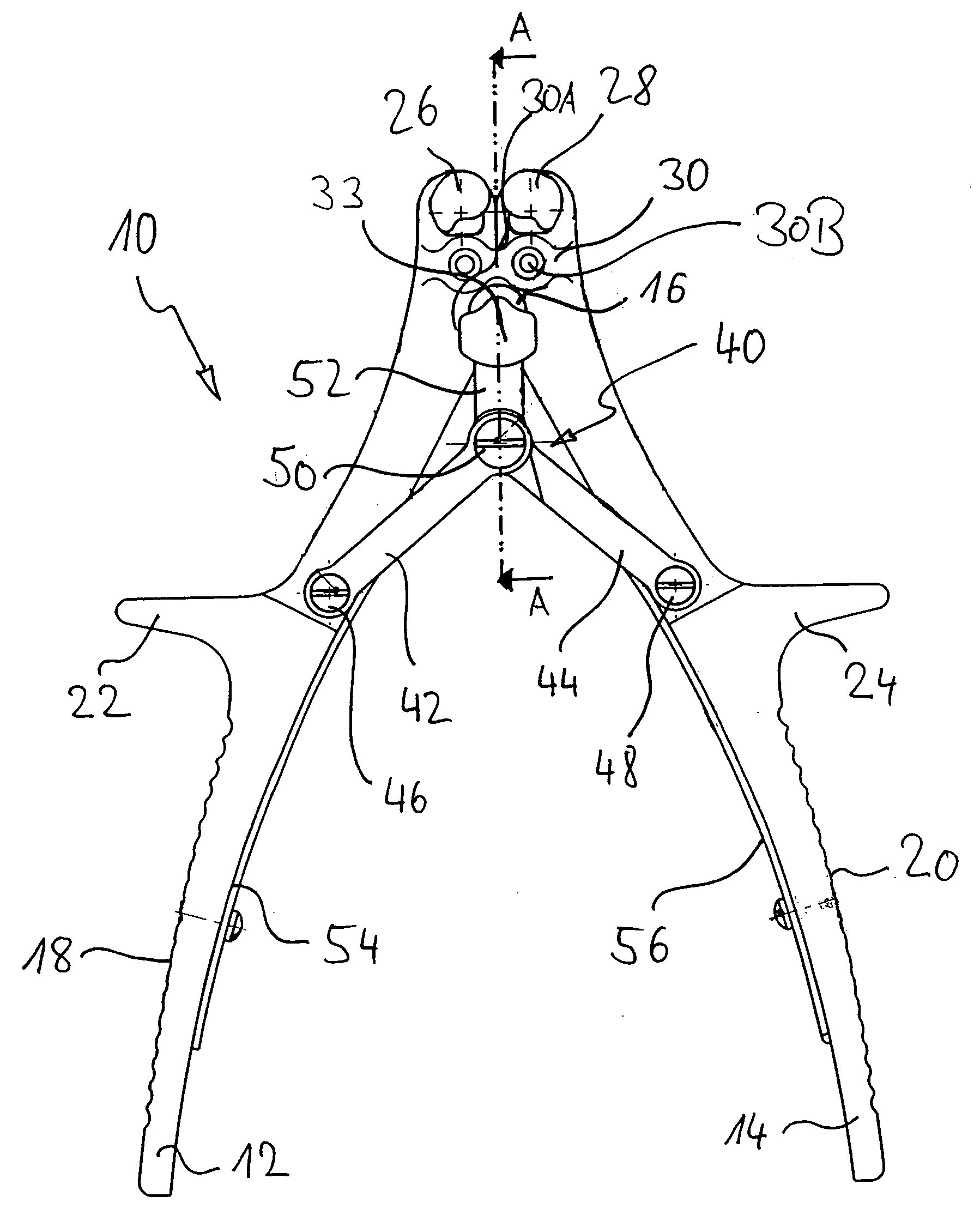
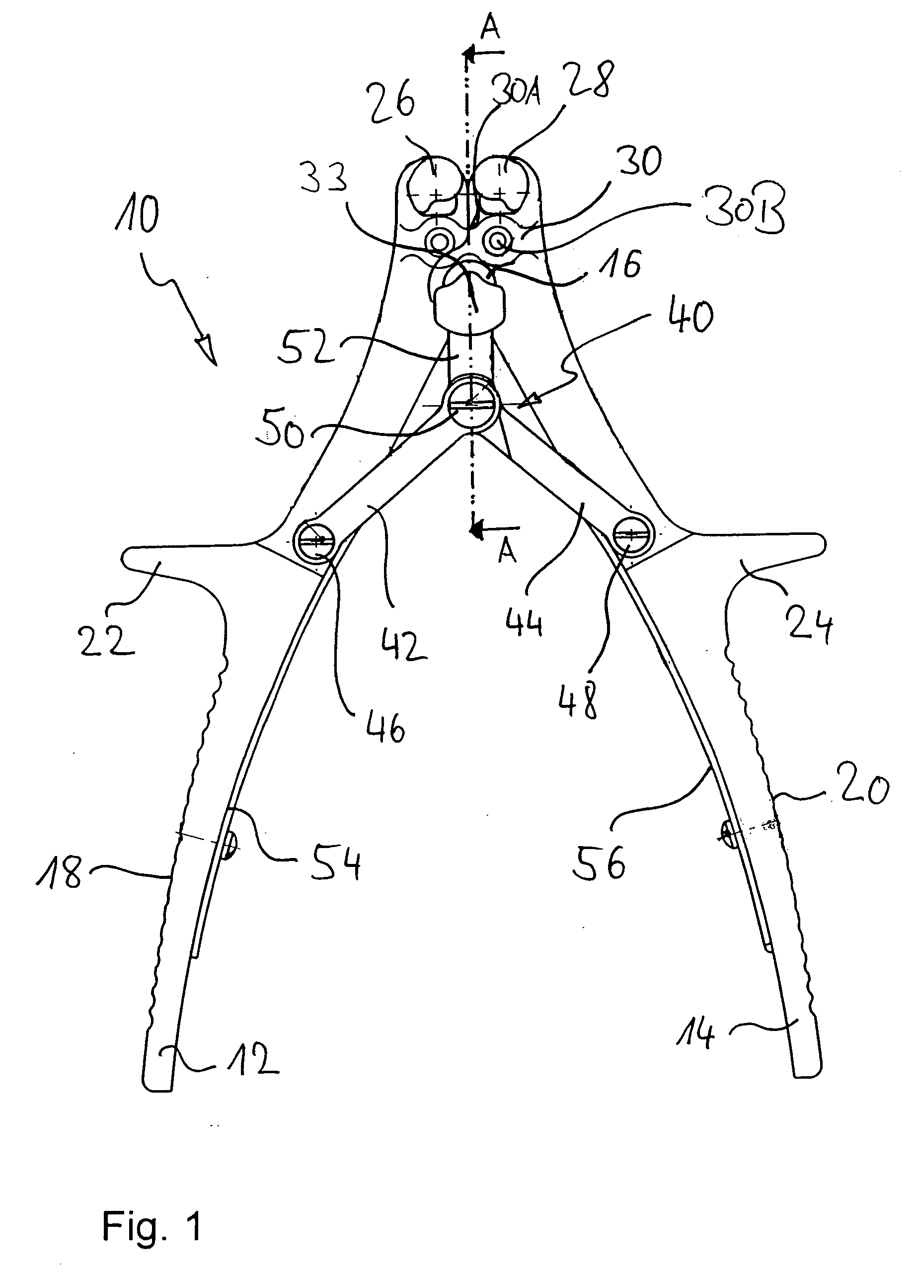
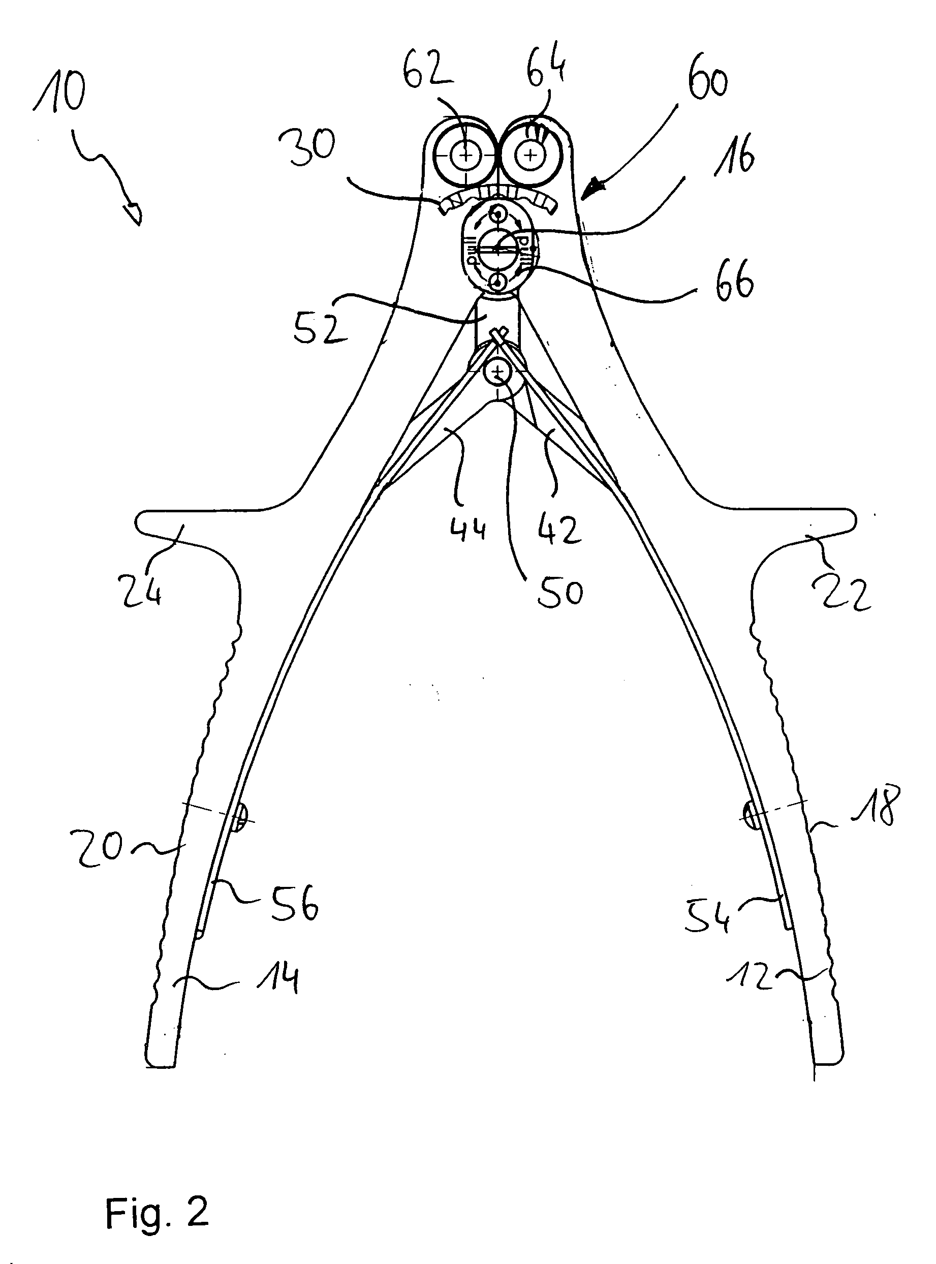
[0019]The first and second counter bearings and the first and second bending punches can be provided at different positions on one and the same bending forceps. To simplify handling and manipulation, the first counter bearings and the first bending punch are conveniently formed on a first side of the branches, and the second counter bearings and the second bending punch are formed on a second side of the branches opposite the first side.

Problems solved by technology

One disadvantage is for example the fact that the bending punch can be deflected only to a limited extent.
On account of this limited deflectability the area of application of the bending forceps is basically limited to bone plates with narrowly defined geometrical dimensions.
However, during a bending procedure the swivelling movement of the bending punch can have a destabilising effect on the position of the bone plate to be bent.

Method used


Image

  • Surgical Bending Forceps and Bending Forceps System
  • Surgical Bending Forceps and Bending Forceps System
  • Surgical Bending Forceps and Bending Forceps System

Examples


Embodiment Construction

[0026]The invention is described hereinafter with the aid of an embodiment of multifunctional surgical bending forceps for bone plates. The use of the bending forceps for bending bone plates should obviously be understood only as an example, since the bending forceps are also suitable for bending other surgical elements such as rods or wires, which have no preferred plane. Furthermore it should be pointed out that the example of implementation relates to multifunctional bending forceps with two separate mechanisms, namely on the one hand a mechanism for bending the bone plate in a preferred plane, and on the other hand a mechanism for bending outwardly from the preferred plane. It is understood per se that one of the two mechanisms could also be omitted or modified.

[0027]FIG. 1 shows a front view of bending forceps according to a preferred embodiment, generally identified by the reference numeral 10, with two branches 12, 14. The two branches 12, 14 can in the example of implementat...


PUM


Abstract

Bending forceps (10) for surgical elements such as bone plates (30) are described. The bending forceps (10) have two branches (12, 14) which can pivot relative to one another and with together two counter bearings (26, 28) for the surgical element to be bent. A bending punch (32) for co-operation with the surgical element is provided in a region between the two counter bearings (26, 28). An actuating movement (40) of the branches (12, 14) is converted into a linear movement of the bending punch (32) in the direction of the surgical element by means of an actuating device (40), for example an elliptical linkage gear mechanism.

Description

FIELD OF THE INVENTION[0001]The present invention relates to bending forceps for surgical elements, such as are used for example for bending bone plates for the craniomaxillofacial region. The invention also relates to a bending forceps system comprising the bending forceps.BACKGROUND OF THE INVENTION[0002]As a preliminary to or during a surgical intervention it is often necessary to adapt and match implants and other surgical elements to anatomical circumstances. The anatomical circumstances can be determined for example by the curvature of a bone or the course of a fracture. In order to adapt surgical elements to anatomical circumstances, the surgeon has a wide range of instruments at his disposal. This range of instruments includes for example cutting forceps, bending forceps, plate benders and similar instruments.[0003]From U.S. Pat. No. 4,474,046 three-point bending forceps for surgical rods are known. The bending forceps have two branches that can swivel about a common axis of...

Claims


Application Information

Patent Timeline
IPC IPC(8): A61B17/58A61B17/28
CPCA61B17/8863
Inventor SCHMUCK, MANFREDGREINER, KARLKLEIN, LUDGER
Owner STRYKER EURO OPERATIONS HLDG LLC
Learn More