Semiconductor light receiving element
- Summary
- Abstract
- Description
- Claims
- Application Information
AI Technical Summary
Benefits of technology
Problems solved by technology
Method used
Image
Examples
first embodiment
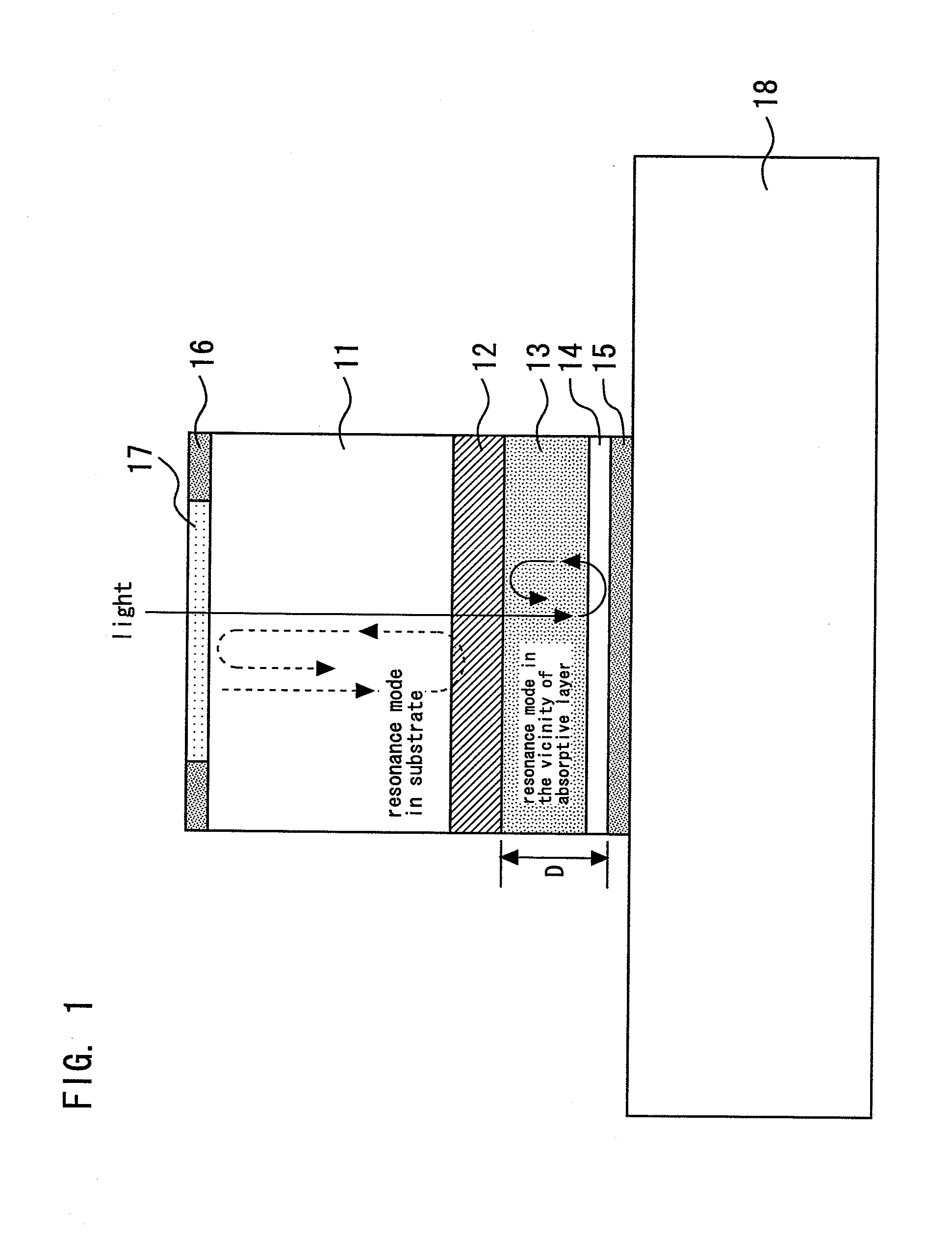
[0026]FIG. 1 is a sectional view showing a semiconductor light receiving element according to the first embodiment of the present invention. The semiconductor light receiving element according to the present embodiment is a backside incidence resonance photodiode (PD) receiving light radiated from the upper side of the drawing.
[0027]An n-type InP substrate 11 (semiconductor substrate) has a lower surface (first major surface) and an upper surface (second major surface) opposite to each other. An n-type multilayer reflective layer 12 (first reflective layer), an absorptive layer 13, a p-type phase adjusting layer 14 (phase adjusting layer), and an anode 15 (second reflective layer) are formed sequentially on the lower surface of the n-type InP substrate 11 from the side of the n-type InP substrate 11. A cathode 16 is formed on the upper surface of the n-type InP substrate 11. The cathode 16 has an opening for receiving light. An anti-reflection film 17 is formed in the opening of the...
second embodiment
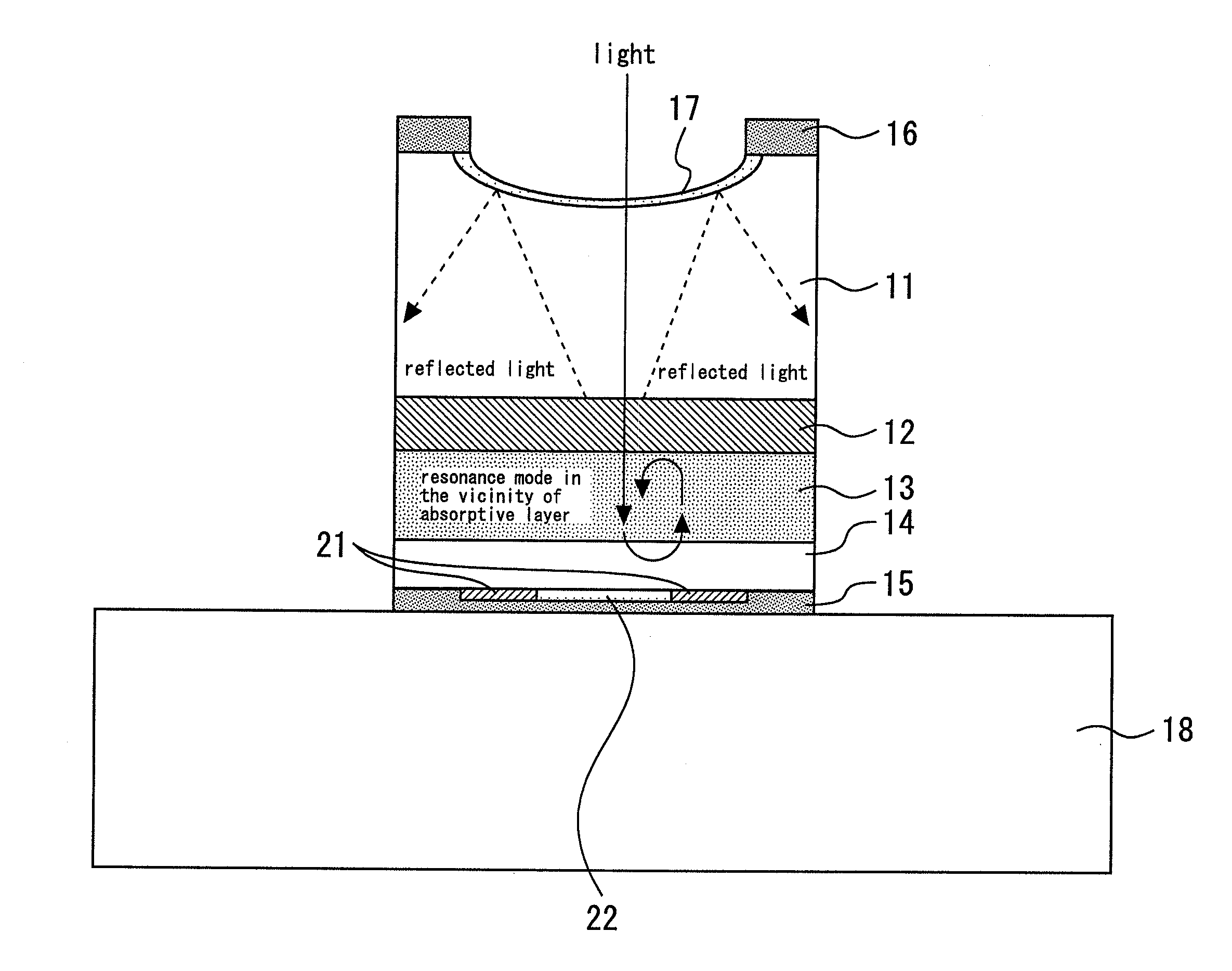
[0042]FIG. 4 is a sectional view showing a semiconductor light receiving element according to the second embodiment of the present invention. A ring-shaped contact layer 21 is disposed on the peripheral portion of an anode 15 (second reflective layer) disposed in a light-receiving region, and is connected to a p-type phase adjusting layer 14. As the contact layer 21, a semiconductor layer having a smaller band gap than a band gap of the p-type phase adjusting layer 14, such as InGaAs and InGaAsP layers, or a metal having low contact resistance, such as AuZn, is used. Other configurations are identical to the configuration of the first embodiment.
[0043]Since the contact resistance of the anode 15 and the p-type phase adjusting layer 14 is lowered by the contact layer 21, heat generation is suppressed, and quantum efficiency is stabilized. The contact layer 21 may be provided on the entire surface between the p-type phase adjusting layer 14 and the anode 15. However, since the contact...
third embodiment
[0044]FIG. 5 is a sectional view showing a semiconductor light receiving element according to the third embodiment of the present invention. A reflection enhancing layer 22 (second reflective layer) having a high reflectivity is provided in the light-receiving region receiving light on a p-type phase adjusting layer 14. A ring-shaped contact layer 21 is disposed on the peripheral portion of the reflection enhancing layer 22, and is connected to the p-type phase adjusting layer 14. An anode 15 (metal film) is provided on the reflection enhancing layer 22 and the contact layer 21. Other configurations are identical to the configuration of the first embodiment.
[0045]By providing the reflection enhancing layer 22, the quantum efficiency of the PD can be further elevated. As the reflection enhancing layer 22, a single-layer or multilayer film of a dielectric material, such as Si3N4, SiO2, amorphous Si, Al2O3, and TiO2 can be used. In this case, since the alloying of the p-type phase adju...
PUM
 Abstract
Description
Claims
Application Information
 - R&D
- Intellectual Property
- Life Sciences
- Materials
- Tech Scout
- Unparalleled Data Quality
- Higher Quality Content
- 60% Fewer Hallucinations
Browse by: Latest US Patents, China's latest patents, Technical Efficacy Thesaurus, Application Domain, Technology Topic, Popular Technical Reports.
© 2025 PatSnap. All rights reserved.Legal|Privacy policy|Modern Slavery Act Transparency Statement|Sitemap|About US| Contact US: help@patsnap.com


