
Measuring roller and spray device

Inactive Publication Date: 2009-09-03
WATKINS NATHAN P
View PDF4 Cites 18 Cited by
  • Summary
  • Abstract
  • Description
  • Claims
  • Application Information

AI Technical Summary

Problems solved by technology

However, all of these devices require the user to rely on their best judgment or to monitor the attached measurement device closely and manually spray the paint at the correct location.

Method used


Image

  • Measuring roller and spray device
  • Measuring roller and spray device
  • Measuring roller and spray device

Examples


Embodiment Construction

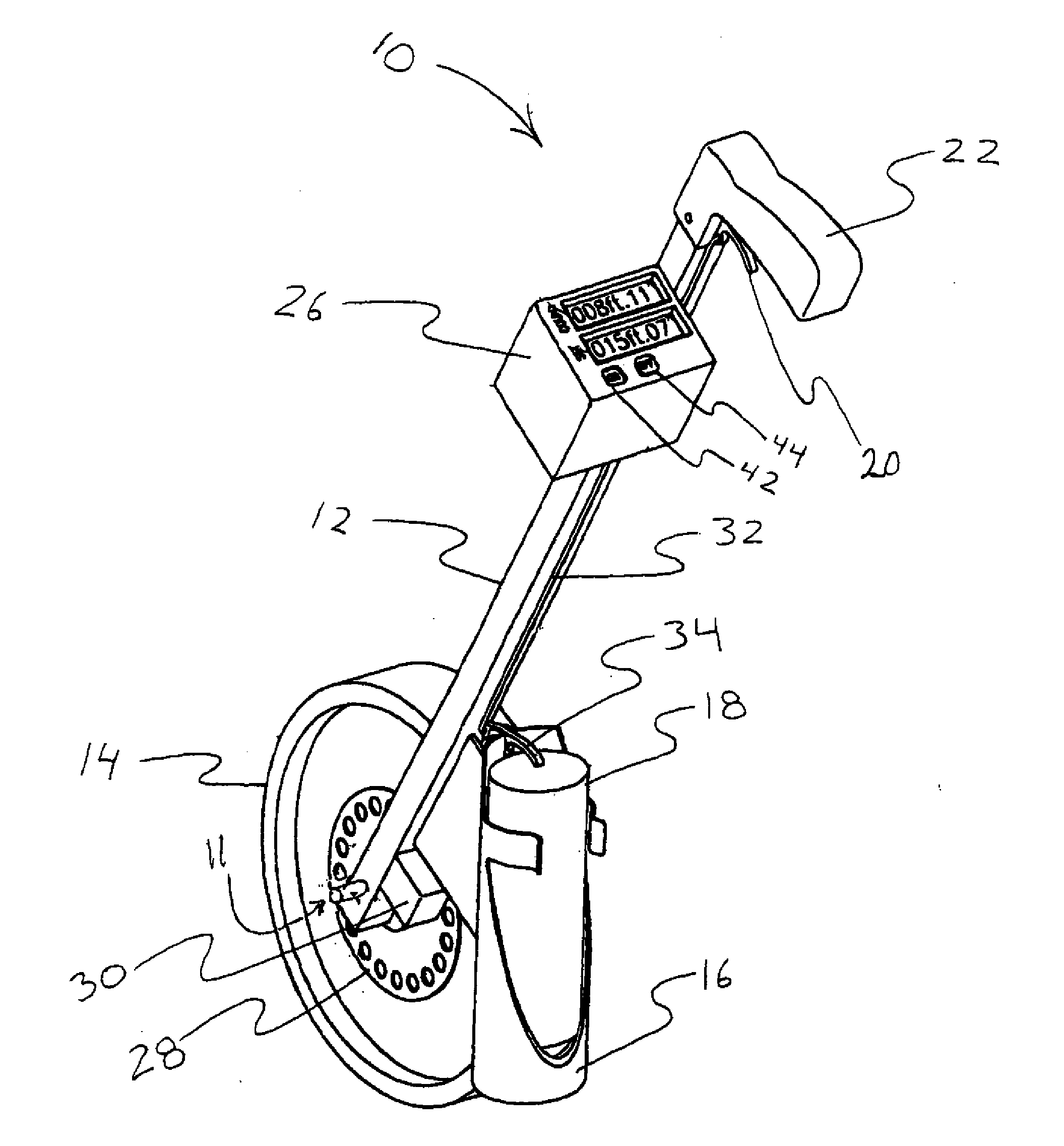
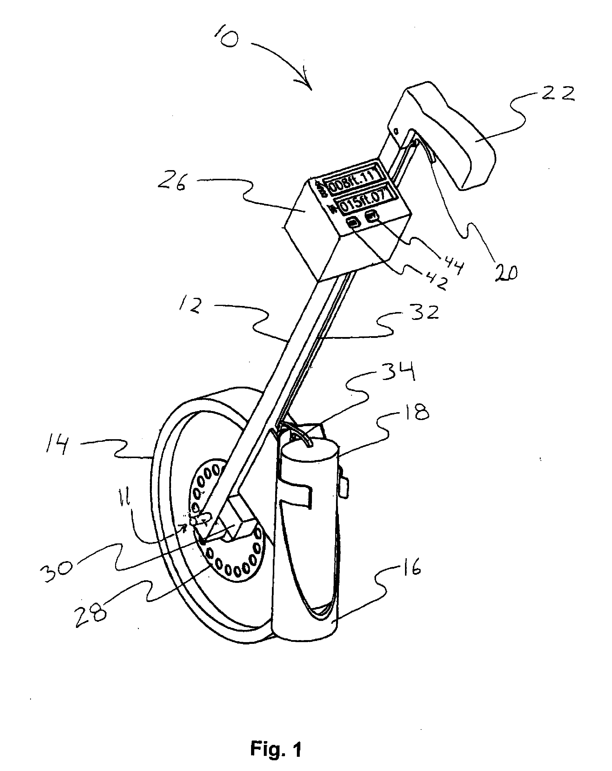
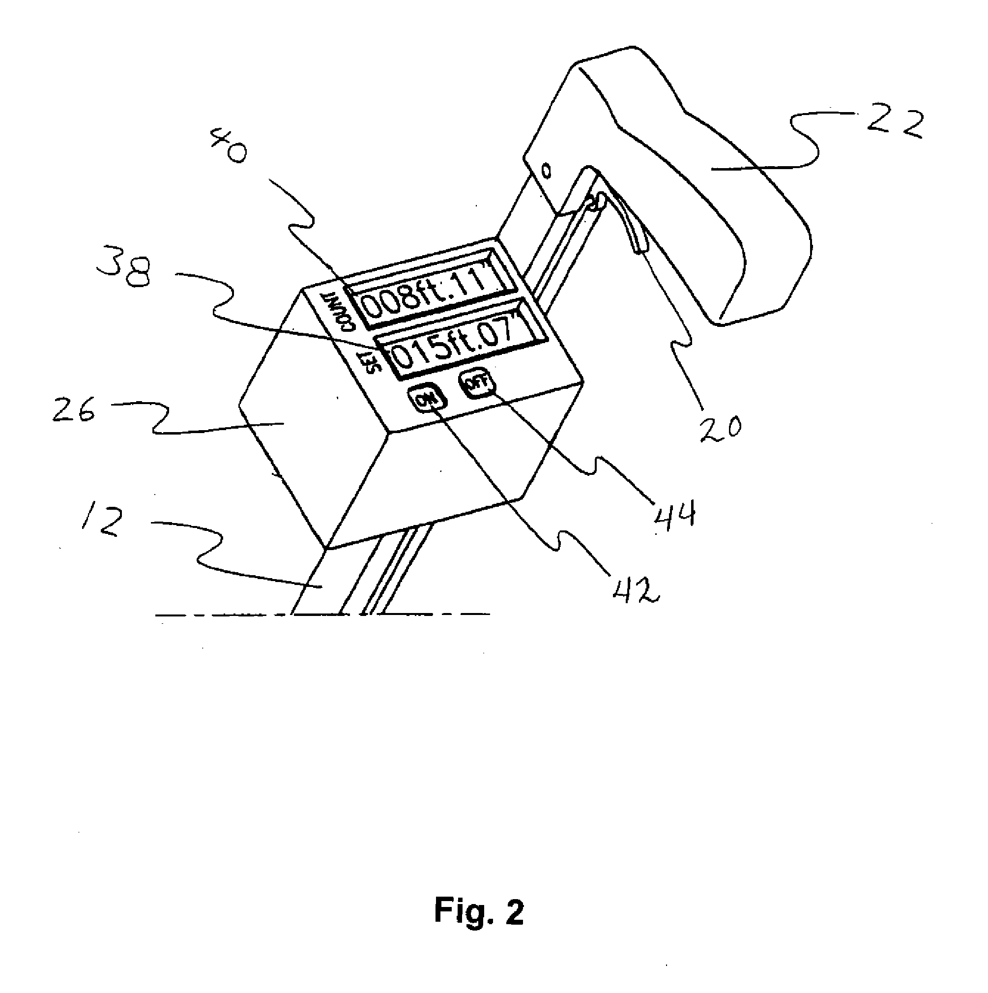
[0040]Referring now specifically to the drawings, an exemplary measuring roller and spray device is illustrated in FIGS. 1-4 and is shown generally at reference numeral 10. An elongate frame 12 has a first end and a second end. A rolling wheel 14 is carried at or near the first end of the frame 12 along with a holder 16 to hold a pressurized can 18 of spray paint or other suitable marking material positioned downward. The second end of the frame 12 is equipped with a trigger 20 positioned below a handle 22 and operable to depress or otherwise actuate the nozzle 24 of the can 18, thereby releasing the spray paint. A control box 26, which displays the distance the rolling wheel 14 has traveled, is located in close proximity to the handle 22. The control box 26 may include a battery or other power supply and a programmable electronic counting and control device (not shown) of a known type

[0041]As illustrated in FIG. 1, an encoder wheel 28 is axially positioned adjacent the rolling whee...


PUM


Abstract

A measuring device includes a frame, a rolling wheel carried by the frame, measuring means for determining a distance traveled by the wheel, and signal means responsive to the measuring means for indicating when the wheel has traveled a preselected set distance. The measuring device may also include marking means such as spray paint, a braking mechanism, and a sonar position indicator.

Description

CROSS REFERENCE TO RELATED APPLICATIONS[0001]This application is a continuation in part application of U.S. patent application Ser. No. 12064495 which in turn is a National Stage application of PCT / US2006 / 033116 which claims priority to U.S. Provisional Application Ser. No. 60 / 710,739 which was filed on Aug. 24, 2005.TECHNICAL FIELD AND BACKGROUND OF THE INVENTION[0002]This invention relates generally to measuring devices, and more particularly to roller and spray devices for marking locations.[0003]Handheld devices that mark the ground with spray paint or other marking substances at the user's direction are well known. These devices rely either on sight or a lever actuated wheel connected to a counter to indicate the appropriate spraying area. They are used, for example, to line fields for outdoor sporting events, such as football, soccer, and baseball. The devices are also used by individuals to mark a surface indicating an underground structure, or to mark the location of landsca...

Claims


Application Information

Patent Timeline
Patent Type & Authority Applications(United States)
IPC IPC(8): G01B3/12
CPCA63C19/06A63C2019/067A63C2203/18G01B3/12G01C22/00B62B5/0485B65D83/203B65D83/26B65D83/386B62B5/0438B05B12/06
Inventor WATKINS, NATHAN P.
Owner WATKINS NATHAN P
Learn More