Ultrasonic Diagnostic Apparatus and Ultrasonic Image Display Method
a diagnostic apparatus and ultrasonic technology, applied in diagnostics, medical science, instruments, etc., can solve the problem of not paying attention to the acquisition of hardness properties
- Summary
- Abstract
- Description
- Claims
- Application Information
AI Technical Summary
Benefits of technology
Problems solved by technology
Method used
Image
Examples
embodiment 1
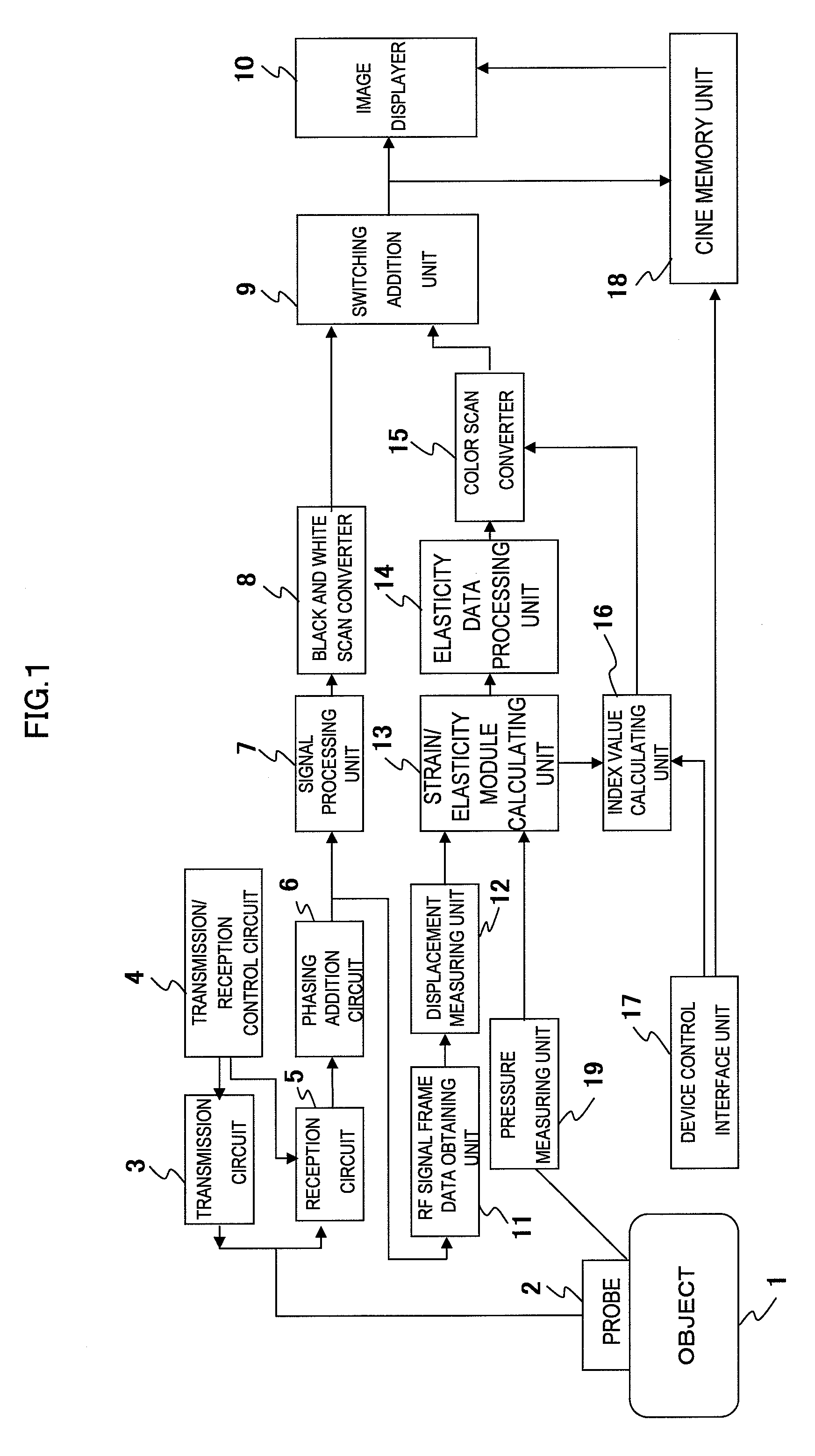
[0057]FIG. 2 is a flow chart of the procedure for generating an indexed elastic image of embodiment 1. The present embodiment is an example for setting reference region R0 to strain image 41 that is one of the elastic images as shown in FIG. 4, and generating indexed elastic image 51 shown in FIG. 5 based on the set reference region and displaying the image.
[0058]First, in step S1 of FIG. 2, a command is issued to strain / elasticity modulus calculating unit 13, and strain image 41 is displayed on image displayer 10. Next, coordinate data of reference region R0 being set manually or automatically using a device such as a mouse is loaded via control interface unit 17 (S2). Then the strain image frame data is loaded from strain / elasticity modulus calculating unit 13, and the average value of the strain in the region corresponding to reference region R0 is calculated as reference strain ε0 (S3). Next, index value Ri,j which is the correlation rate between strain εi,j in each strain measu...
embodiment 2
[0071]In embodiment 1, an example for setting reference region R0 being the reference region for indexing in the living body is described. However, the present invention is not limited to this, and when ultrasonic tomographic data is obtained using probe 2 having reference deformable member 33 which is an elastic member shown in FIG. 3(B), image 53 of reference deformable member 33 is displayed in the tissue region located in the nearest to probe 2 on the strain image as shown in FIG. 6. In the same manner as embodiment 1, indexed elastic image 52 can be generated and displayed by setting reference region R0 in this image region of reference deformable member 33.
[0072]In particular, it is possible to estimate an approximate elasticity module of the tissues in the respective measurement points by measuring elasticity module of reference deformable member 33 in advance. More specifically, by setting elasticity modulus of reference deformable member 33 as Eref(kPa), approximate elastic...
embodiment 3
[0076]While an example is described in embodiment 1 for setting reference region R0 by inputting from control interface 17, reference region R0 can be also set automatically as described below. For example, by detecting the softest region in an image such as an elastic image, and reference region R0 may be set thereto.
[0077]Also, for example, FIG. 7(A) shows B-mode tomographic image 54 of a mammary gland wherein fatty tissues that are positioned nearest to probe 2 appear thereon, which are also the softest tissues in the measurement region. Here, since it is possible to detect the boundary between fat 61 and mammary gland 62 also on B-mode image 54, the region from the vicinity of the body surface to the boundary of the mammary gland can be extracted and automatically set as reference region R0.
[0078]In this case, as shown in FIG. 7(B), indexed elastic image 55 having reference region R0 that is the whole tissue 1 of fatty tissue 61 can be obtained.
[0079]Also, for example, it is pos...
PUM
 Abstract
Description
Claims
Application Information
 - R&D
- Intellectual Property
- Life Sciences
- Materials
- Tech Scout
- Unparalleled Data Quality
- Higher Quality Content
- 60% Fewer Hallucinations
Browse by: Latest US Patents, China's latest patents, Technical Efficacy Thesaurus, Application Domain, Technology Topic, Popular Technical Reports.
© 2025 PatSnap. All rights reserved.Legal|Privacy policy|Modern Slavery Act Transparency Statement|Sitemap|About US| Contact US: help@patsnap.com


