
Insert wall anchor for a grab bar

a technology of wall anchors and grab bars, applied in the field of bars, can solve the problems of not always being able to install, assembly configurations of these mounting configurations have presented some challenges, and the projection dimension can be adversely affected at one end, and achieve the effect of convenient installation and re-usability

Active Publication Date: 2009-08-27
LIBERTY HARDWARE MFG
View PDF34 Cites 8 Cited by
  • Summary
  • Abstract
  • Description
  • Claims
  • Application Information

AI Technical Summary

Benefits of technology

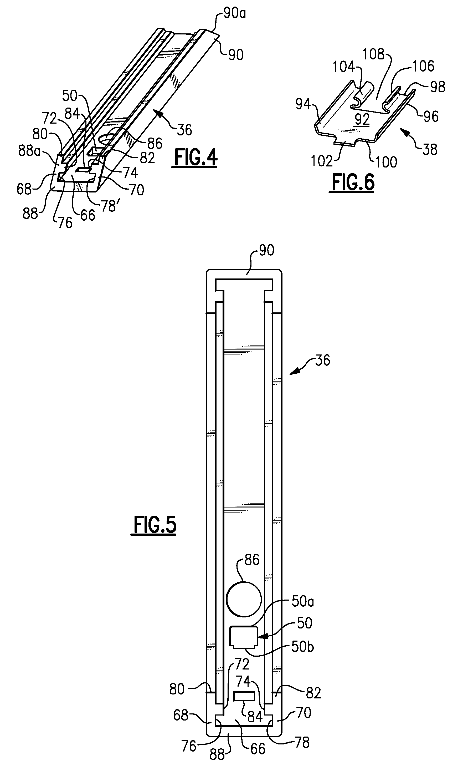
[0010]In one example, the anchor assembly includes a vertical support beam, a flange arm assembly, and a spring. The flange arm assembly has an arm portion and a base portion with a flange that fits against a wall surface. The flange prevents the flange arm assembly from falling behind the wall structure. The spring is attached to the vertical support beam and cooperates with the arm portion to hold the flange arm assembly in place during installation. The arm portion is received within a slot formed within the vertical support beam.

Problems solved by technology

When positioning the grab bars on the wall of the enclosure, it would be ideal that the anchor assemblies be able to be aligned with one of the wall studs; however this is not always possible.
Traditional anchor assemblies for these mounting configurations have presented some challenges.
For example, when one end of the grab bar is mounted to a stud and the other end is mounted only to sheetrock, the projection dimension can be adversely affected at one end due to height variations between the two different mounting configurations.
As such, the anchor cannot be removed and re-used if needed.

Method used


Image

  • Insert wall anchor for a grab bar
  • Insert wall anchor for a grab bar
  • Insert wall anchor for a grab bar

Examples


Embodiment Construction

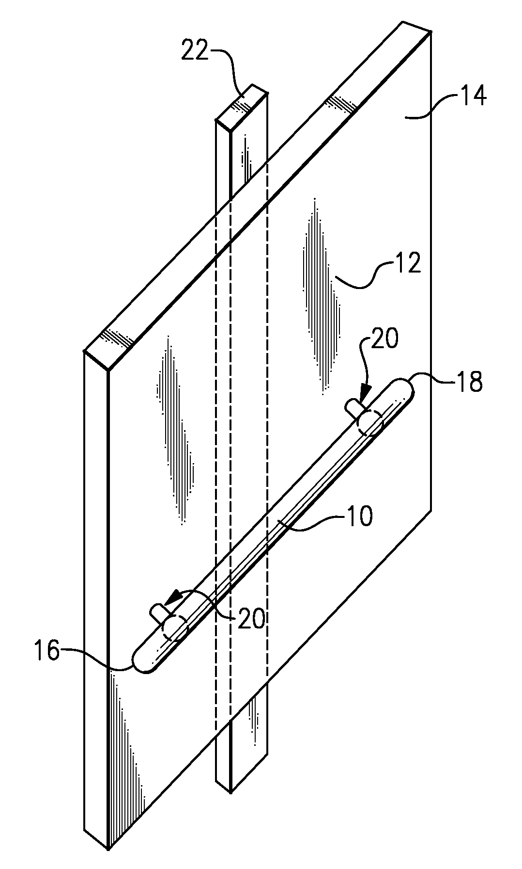
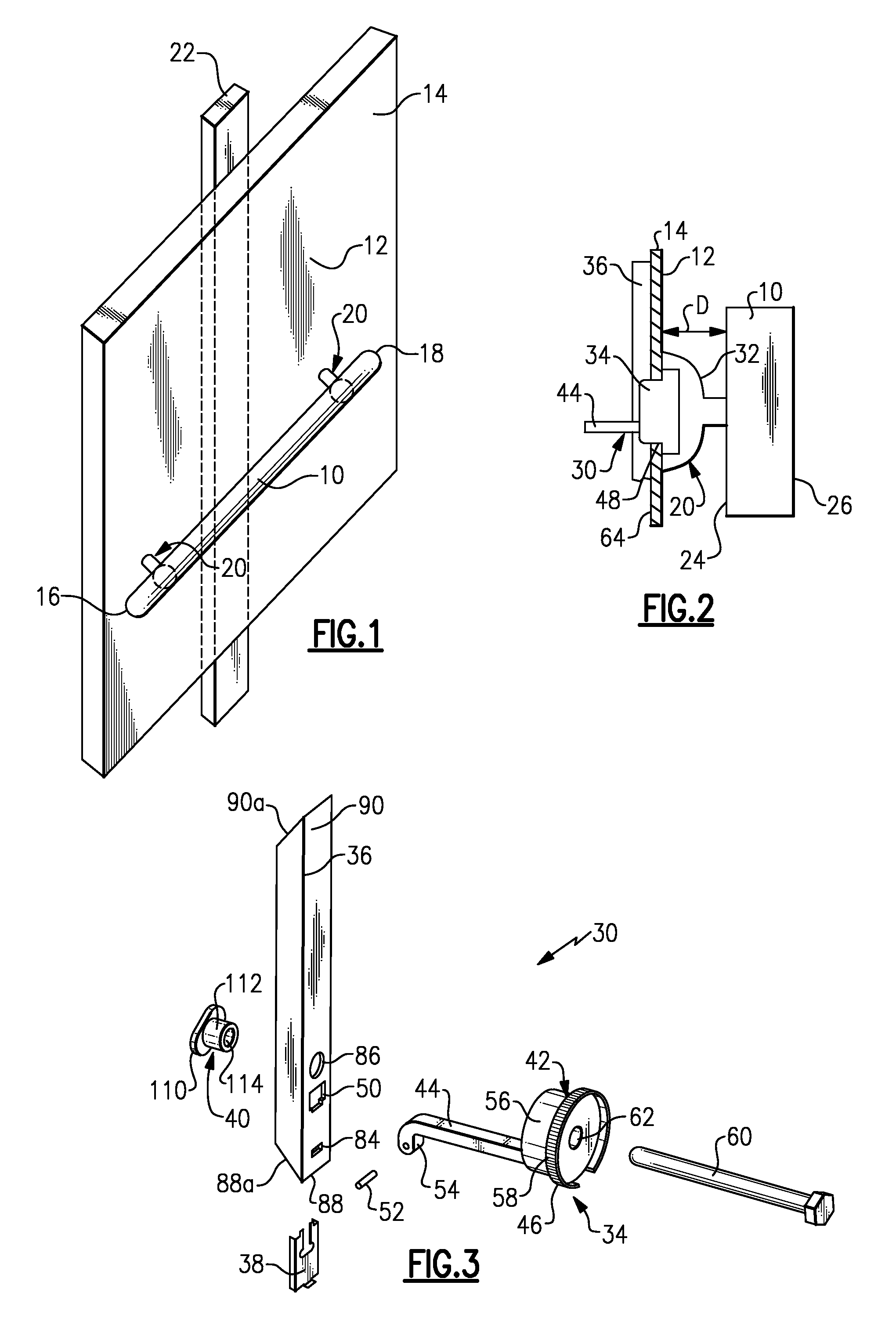
[0024]FIG. 1 shows a grab bar 10 for attachment to a bathroom wall surface 12 of a wall structure 14, such as a tub surround / shower enclosure. The shower enclosure can be made from fiberglass or types of materials suitable for bathroom environments could also be used. The grab bar 10 extends between first 16 and second 18 ends. Mounting assemblies 20 are positioned near each of the first 16 and second 18 ends such that the grab bar 10 can be secured to the wall surface 12. In the example shown in FIG. 1, the grab bar 10 is a generally straight configuration; however, the grab bar 10 could include one or more angled portions or could have a non-linear configuration, such as an oval, triangular, or round shape for example. Further, while two mounting assemblies 20 are shown, it should be understood that a single mounting assembly could be used, or additional mounting assemblies could be used, depending upon the overall configuration of the grab bar.

[0025]In one example, the mounting a...


PUM

PropertyMeasurementUnit
Diameteraaaaaaaaaa

Abstract

A grab bar is attached to a wall with at least one anchor assembly. The anchor assembly can be removed and repeatedly used as needed. The anchor assembly includes a vertical support beam, a flange arm assembly having a base portion and an arm portion, and a spring. The spring is attached to the vertical support beam and cooperates with the arm portion to hold the flange arm assembly in place during installation. The base portion of the flange arm assembly has a flange that fits against a wall surface of the wall structure, and the arm portion is received within a slot formed within the vertical support beam. The flange prevents the flange arm assembly from falling behind the wall structure.

Description

TECHNICAL FIELD[0001]This invention relates to a bar that is utilized in bathrooms, such as a grab bar for example, and more specifically the invention relates to an insert wall anchor used to secure the grab bar to a wall.BACKGROUND OF THE INVENTION[0002]Grab bars are utilized in bathroom applications to provide support for an individual during exit or entry in a bathtub or shower, for example. Typical grab bars include a body member that is spaced apart from, and parallel to, a wall. The grab bar has end mounts that extend toward the wall such that the grab bar can be mounted to the wall. Anchor assemblies are mounted to a wall structure that forms the shower enclosure or tub surround, and the end mounts of the grab bar are then attached to the anchor assemblies.[0003]Behind the wall structure is a plurality of studs that extend in a vertical direction from a floor to a ceiling. Sheetrock panels are attached to the studs to form the wall structure that provides an enclosed space f...

Claims


Application Information

Patent Timeline
IPC IPC(8): F16B21/00A47K17/02B23P19/04
CPCA47K17/022Y10T29/53A47K2201/025F16B13/10F16B13/04F16B13/08
Inventor BOWDEN, ROHNFORREST, EARL DAVIDGRAFF, ANDREW JAMES
Owner LIBERTY HARDWARE MFG
Learn More