
Joystick and method of manufacturing the same

a technology of hall effect sensor and joystick, which is applied in the field of joysticks, can solve the problem of high manufacturing cost of the manufacturing process

Active Publication Date: 2009-08-27
DANFOSS POWER SOLUTIONS INC
View PDF16 Cites 113 Cited by
  • Summary
  • Abstract
  • Description
  • Claims
  • Application Information

AI Technical Summary

Benefits of technology

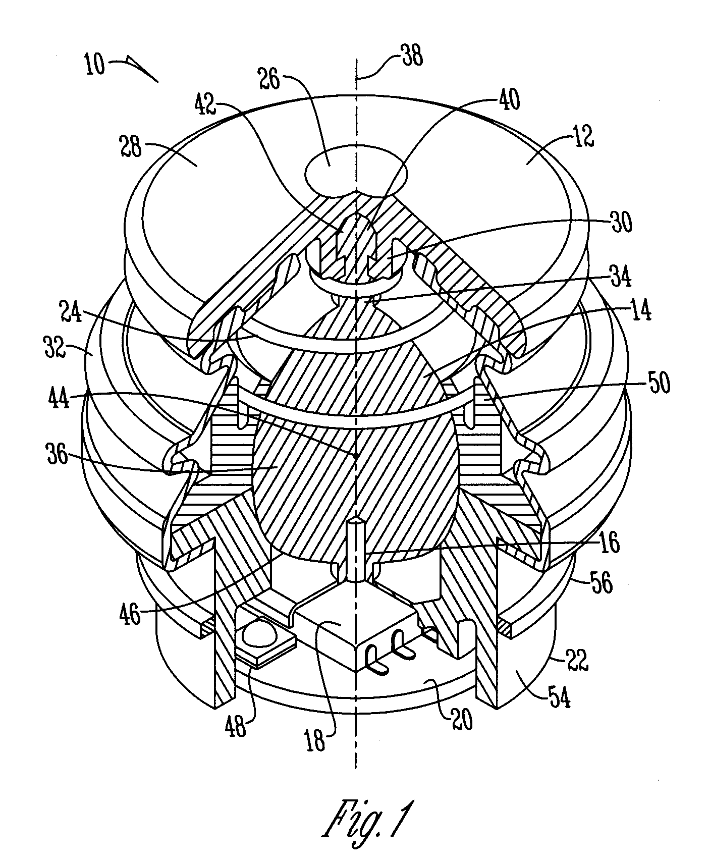
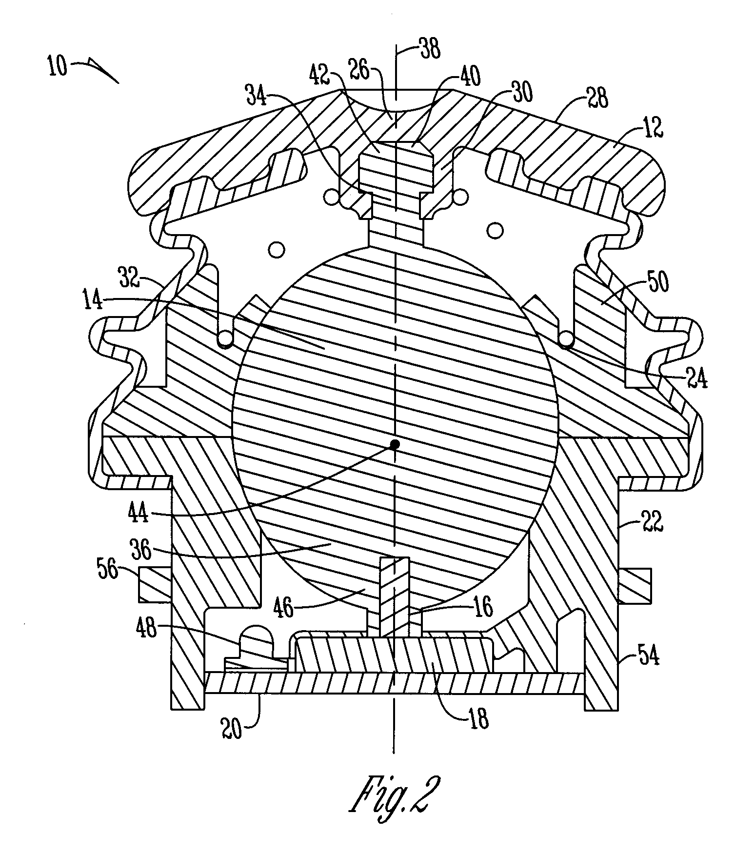
[0008]A joystick having a movable member that is of one-piece construction that extends from a shaft portion to a spherical portion wherein the diameter of the shaft portion is less than the diameter of the spherical portion. An actuating member is secured to the shaft portion of the movable member to provide actuation of the movable member. A magnet is disposed within the spherical portion of the movable member at the bottom of the sphere extending upwardly and is off center from a center point of the spherical portion. A three axis sensor is disposed underneath, adjacent, and in spaced relation to the spherical portion and magnet of the movable member such that movement of the actuating member positions the magnet in a hemispherical pattern along the three axis sensor.

Problems solved by technology

As a result of the multiple pieces provided to manufacture this joystick the manufacturing process is expensive.

Method used


Image

  • Joystick and method of manufacturing the same
  • Joystick and method of manufacturing the same
  • Joystick and method of manufacturing the same

Examples


Embodiment Construction

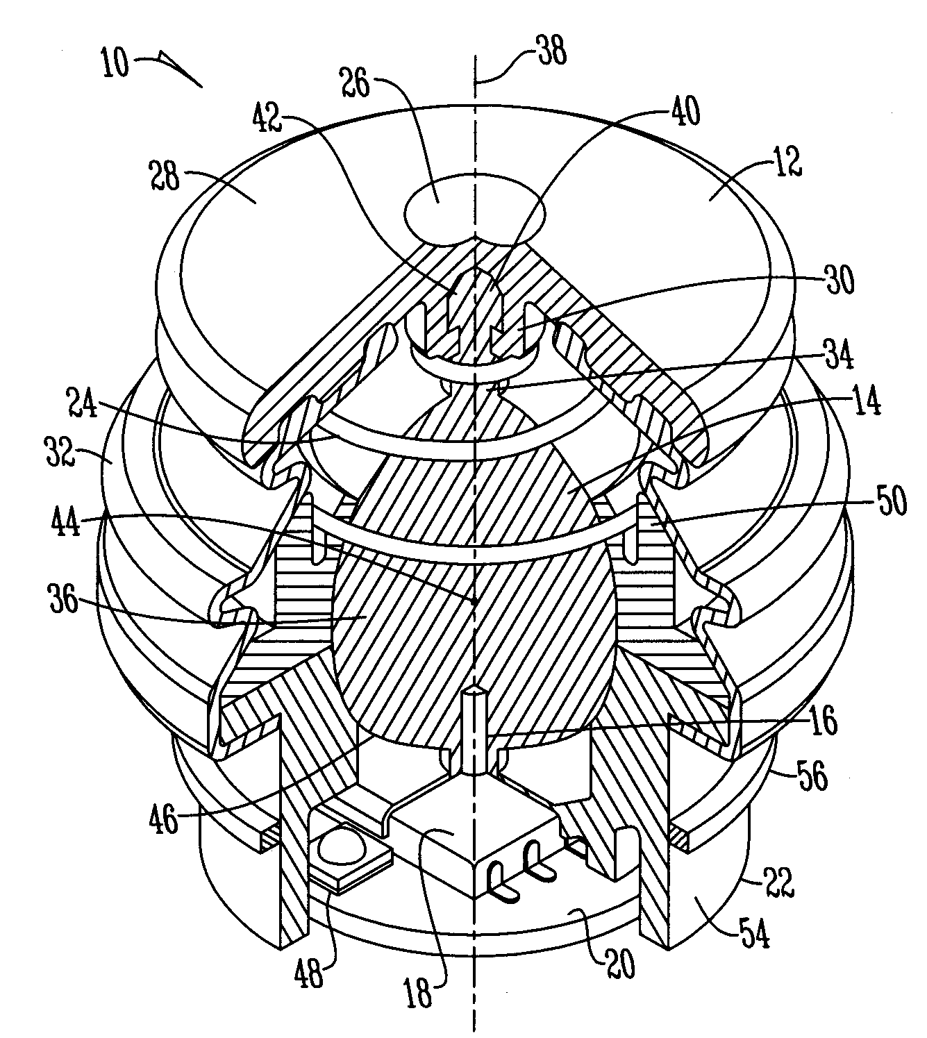
[0011]The figure shows a joystick 10 that is comprised of an actuating member 12 such as a knob that is used to actuate a movable member 14 that contains a magnet 16 disposed therein such that movement of the movable member 14 is sensed by a three axis sensor 18. The three axis sensor is electrically connected to a PBC (printed circuit board) 20 and the components are disposed within a housing 22 wherein a conical spring 24 connects the housing 22 to the movable member 14. While the three axis sensor 18 may be any sensor that is able to detect three axes of movement in a preferred embodiment the three axis sensor 18 is a three axis Hall Effect sensor. Additionally, the actuating member 12 is able to move in any axial direction and is biased by the conical spring 24 to a non-actuated or neutral position wherein no net force is provided on the actuating member 12.

[0012]The actuating member 12 is conically shaped having a centrally located concave portion 26 located on a top surface wh...


PUM


Abstract

A joystick having a movable member that includes a shaft portion and a spherical portion wherein the shaft portion has a diameter less than the spherical portion. An actuating member is secured to the shaft portion of the movable member to provide actuation of the movable member. A magnet is disposed within the spherical portion of the movable member and positioned adjacent a three axis sensor such that the magnet moves in a hemispherical pattern along the three axis sensor to operate a device.

Description

BACKGROUND OF THE INVENTION[0001]This invention relates to joysticks. More specifically, this invention relates to a joystick using a three axis Hall Effect sensor in order to provide operation of a device.[0002]Joysticks have been used for many years for varying operations. Joysticks not only have been used in gaming arts but additionally have been used in association with hydraulic devices such as cranes, fork lifts and the like. Specifically, joysticks allow for compact multi-dimensional actuation of a device. Known in the art are several types of joysticks including joysticks based on a “gimbal” mechanism wherein a magnet moves on a hemisphere centered at the IC (the sensor). Specifically, axial magnetization is provided wherein the flux density is provided through the following equations:Bx=SIN(α)COS(β)By=COS(α)SIN(β)Bz=COS(α)COS(β)[0003]Another type of joystick that exists is considered a “ball and socket” joint wherein the magnet moves on a hemisphere centered about the pivot...

Claims


Application Information

Patent Timeline
Patent Type & Authority Applications(United States)
IPC IPC(8): G05G1/04H01L43/04H01H3/04
CPCG05G5/05G05G9/047G05G25/04Y10T74/20171G05G2009/04755Y10T74/20201G05G2009/04707G05G9/04737
Inventor OLSON, JESSE W.KRUEGER, JOSEPH K.
Owner DANFOSS POWER SOLUTIONS INC
Learn More