
Method and apparatus for power conversion with wide input voltage range

a power conversion and input voltage technology, applied in the direction of electric variable regulation, process and machine control, instruments, etc., can solve the problems of small power loss, limited input voltage range, low power loss,

Active Publication Date: 2009-08-27
MURATA POWER SOLUTIONS
View PDF13 Cites 52 Cited by
  • Summary
  • Abstract
  • Description
  • Claims
  • Application Information

AI Technical Summary

Benefits of technology

[0020]Other features, elements, steps, characteristics, aspects and advantages of the present invention will become m

Problems solved by technology

In the ON state, the switch can conduct a relatively large current at near zero voltage across its terminals, resulting in a low power loss.
In the OFF state, a relatively large voltage can be applied to the switch, but the current is near zero, resulting again in a very small power loss.
Because the minimum pulse width is limited in practice, the input voltage range is limited.
This results in larger filters and consequently larger converter sizes.
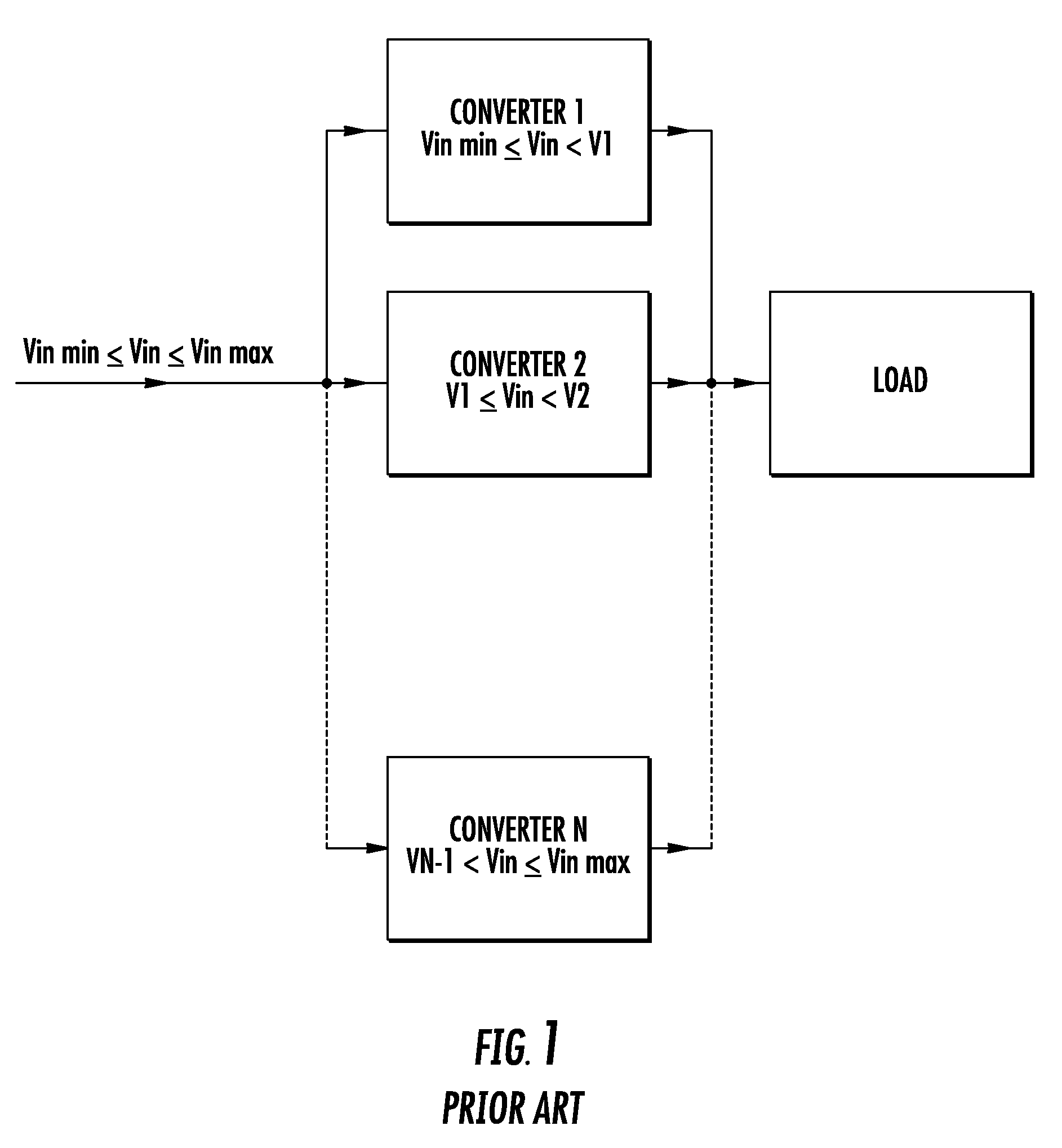
A disadvantage of this known parallel structure is an increased number of power converters, where each power converter is designed for full power, which leads to increased size and cost of the power conversion system.

Method used


Image

  • Method and apparatus for power conversion with wide input voltage range
  • Method and apparatus for power conversion with wide input voltage range
  • Method and apparatus for power conversion with wide input voltage range

Examples


Embodiment Construction

[0045]Preferred embodiments of the present invention will be described with respect to FIGS. 2-17.

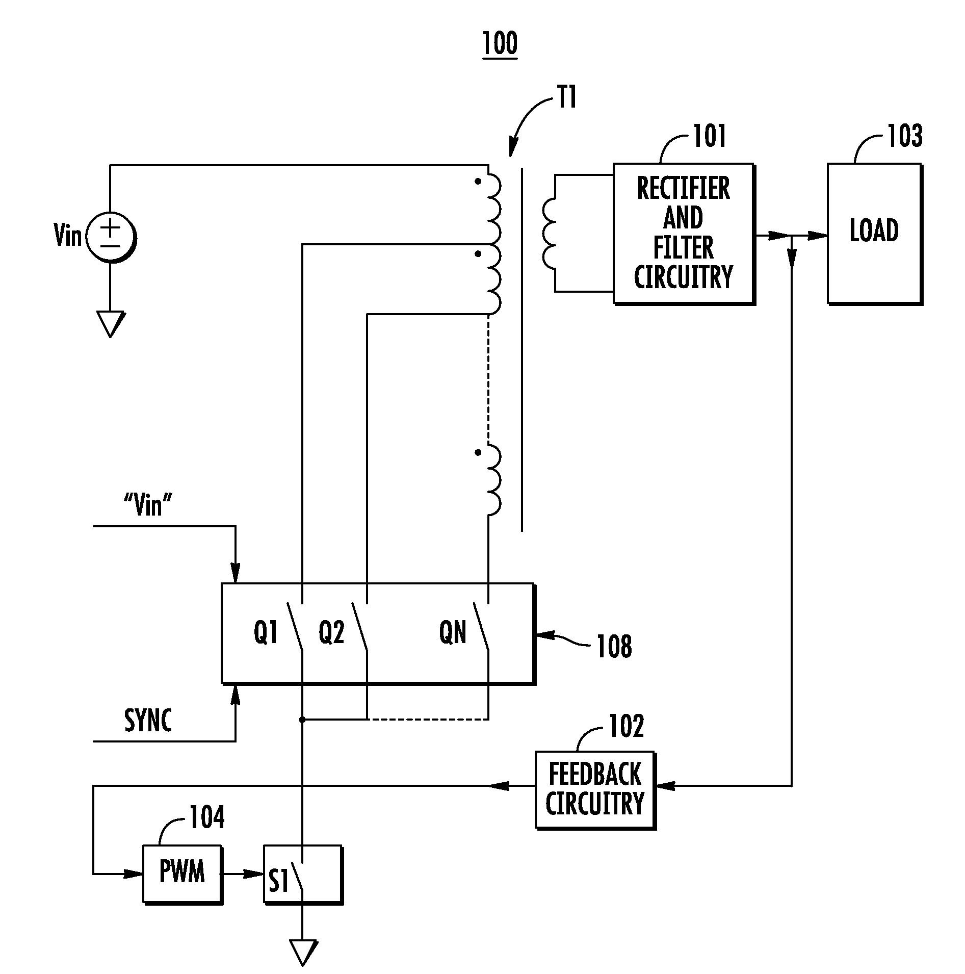
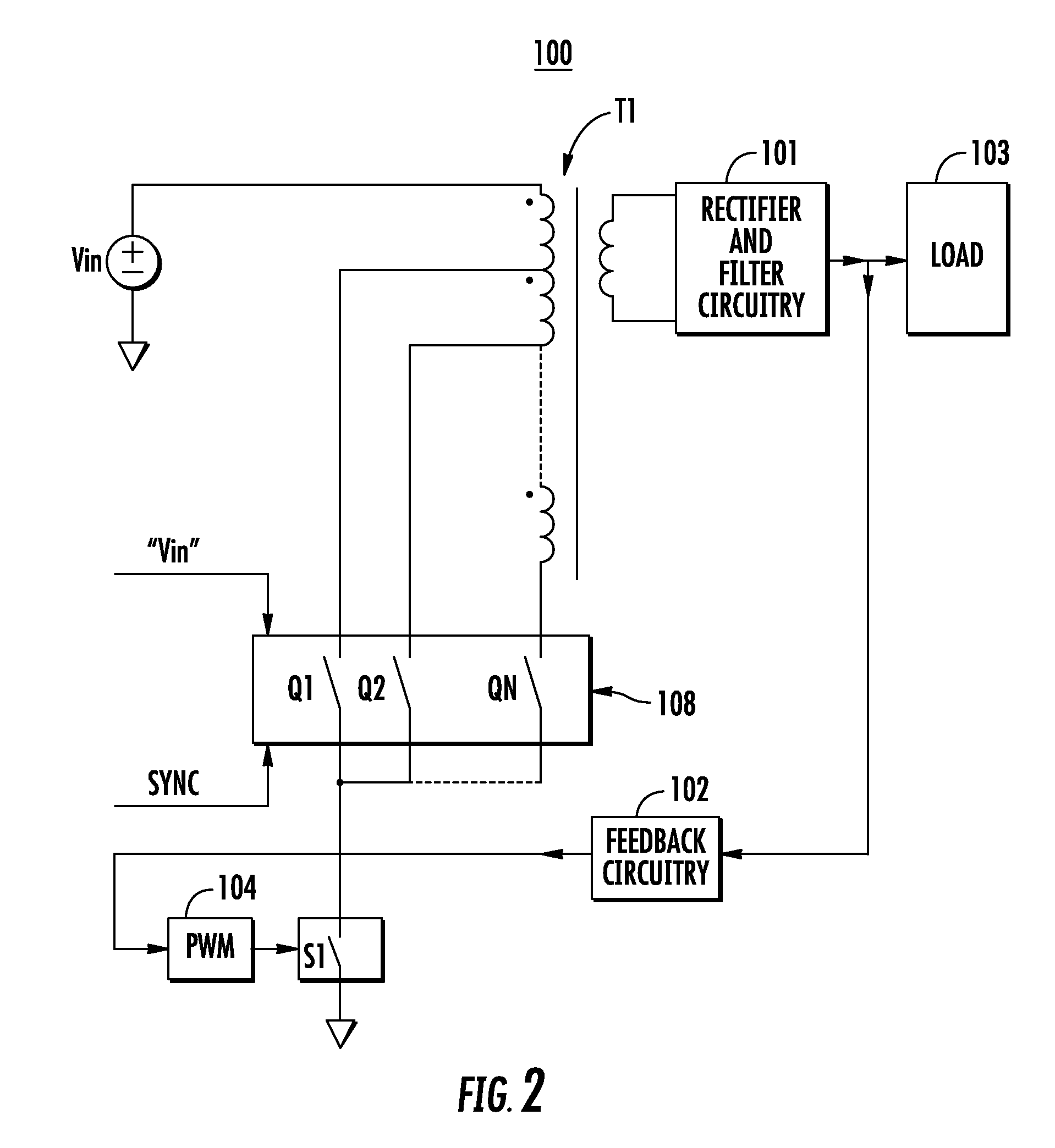
[0046]According to preferred embodiments of the present invention, both the duty ratio, D, and turns ratio, TR, of the power transformer are controlled. The input voltage range v=Vin max / Vin min is divided into N sub-ranges (or subintervals) in such a way that TR=TRi (i=1, 2, . . . , N—where N is the number of sub-ranges) is constant within each sub-range. Typically, all of the sub-ranges (a ratio between the maximum, Vi max, and the minimum, Vi min, input voltages within a sub-range number i) are selected equally such that:

VimaxVimin=K=v1N.

[0047]For buck derived topologies, because TR is constant within each sub-range, a sub-range is equal to the duty cycle range d=Dmax / Dmin:

K=v1N=d,

consequently,

N=LOGd(v)=LOG(v)LOG(d).

[0048]At low input voltages, within the first sub-range, the turns ratio TR is set at minimum (TR=TRmin); at medium input voltages, the turns ratio TR is set higher; and ...


PUM


Abstract

A power conversion system includes an input terminal that is arranged to be connected to a voltage source; a transformer having a first winding connected to the input terminal and a second winding connected to an output terminal of the power conversion system, either the first winding or the second winding is provided with at least three taps that are arranged to divide the first winding or the second winding into at least two sub-windings; at least one tap switch connected to the at least two sub-windings; a control circuit connected to the at least one tap switch; and at least one switch connected to the at least one tap switch. The control circuit is arranged to control the at least one tap switch to control the turn ratio of the transformer.

Description

BACKGROUND OF THE INVENTION[0001]1. Field of the Invention[0002]The present invention relates, in general, to switching mode power supplies and power conversion system, and in particular to methods and apparatuses for power conversion with wide input voltage range. The present invention can be used in a standalone converter or as part of a larger system. For example, one application of the present invention is to provide an apparatus that can increase the output voltage holdup time in off-line power supplies during a loss of input power.[0003]2. Description of the Related Art[0004]Power devices such as MOSFETs, for example, used in known switching mode power supplies (SMPS) and converters work as high frequency (typically hundreds of kilohertz) ON / OFF switches. In the ON state, the switch can conduct a relatively large current at near zero voltage across its terminals, resulting in a low power loss. In the OFF state, a relatively large voltage can be applied to the switch, but the c...

Claims


Application Information

Patent Timeline
IPC IPC(8): H01F21/00
CPCH02M1/10H02M3/33576H02M3/33569H02M3/33573H02M3/33571
Inventor ASINOVSKI, ALEXANDERWANES, JOHNOZKAYNAK, ISAACDRAGOJEVIC, MILAN
Owner MURATA POWER SOLUTIONS
Learn More