
Control device and control method for internal combustion engine

a control device and control method technology, applied in the direction of electrical control, process and machine control, instruments, etc., can solve the problems of deteriorating driveability, foregoing technology, deteriorating driveability or deteriorating combustion

Active Publication Date: 2009-08-20
TOYOTA JIDOSHA KK
View PDF7 Cites 21 Cited by
  • Summary
  • Abstract
  • Description
  • Claims
  • Application Information

AI Technical Summary

Benefits of technology

[0018]However, according to the foregoing control device for an internal combustion engine, even in the case where a blended fuel is used as the fuel, the above-described output correction process is performed, so that the produced output is corrected on the basis of a difference in the specifically determined fuel property. For example, in the case where an injection amount exceeding the range of the injection amount that the fuel injection device can properly inject is required, an injection amount that does not exceed that range is supplied to produce the output. As a result, even during the high load region, the fuel is properly injected, so that the driveability can be suitably secured. At this time, although there is a possibility of the output reducing to some extent, large or small, the reduction can be eliminated if a countermeasure, such as provision of a device that supplements the output as described below, is taken.
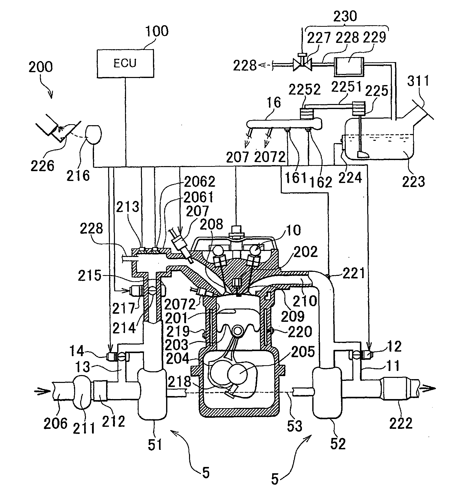
[0044]According to the control device for the internal combustion engine as described above, the fuel property is suitably specifically determined, and the output can be stabilized. Specifically, the fuel property, for example, the alcohol concentration, the blend proportion, etc., is specifically determined directly or indirectly by the fuel property specific determination device, such as the fuel property sensor provided for the fuel tank that stores fuel. Using the fuel property specifically determined in this manner, the output can be stabilized.

Problems solved by technology

For example, if the amount of fuel injection is reduced when an idle operation is being performed following the completion of cranking and the engine rotation speed is a low speed, for example, an idling rotation speed, a drop in the engine rotation speed to below the idling rotation speed occurs, and degrades the driveability (e.g., causing a lean misfire, knocking, faults due to an exhaust gas temperature rise, etc.).
However, the foregoing technology disclosed in Japanese Patent Application Publication No. 2006-2706 (JP-A-2006-2706) can suffer from the following problems.
That is, at the time of full load, a proper injection amount cannot be secured or the injection end timing may become retarded, and therefore the output produced may become lower than an assumed value or may become unstable, thus resulting in a deteriorated driveability or a deteriorated combustion.
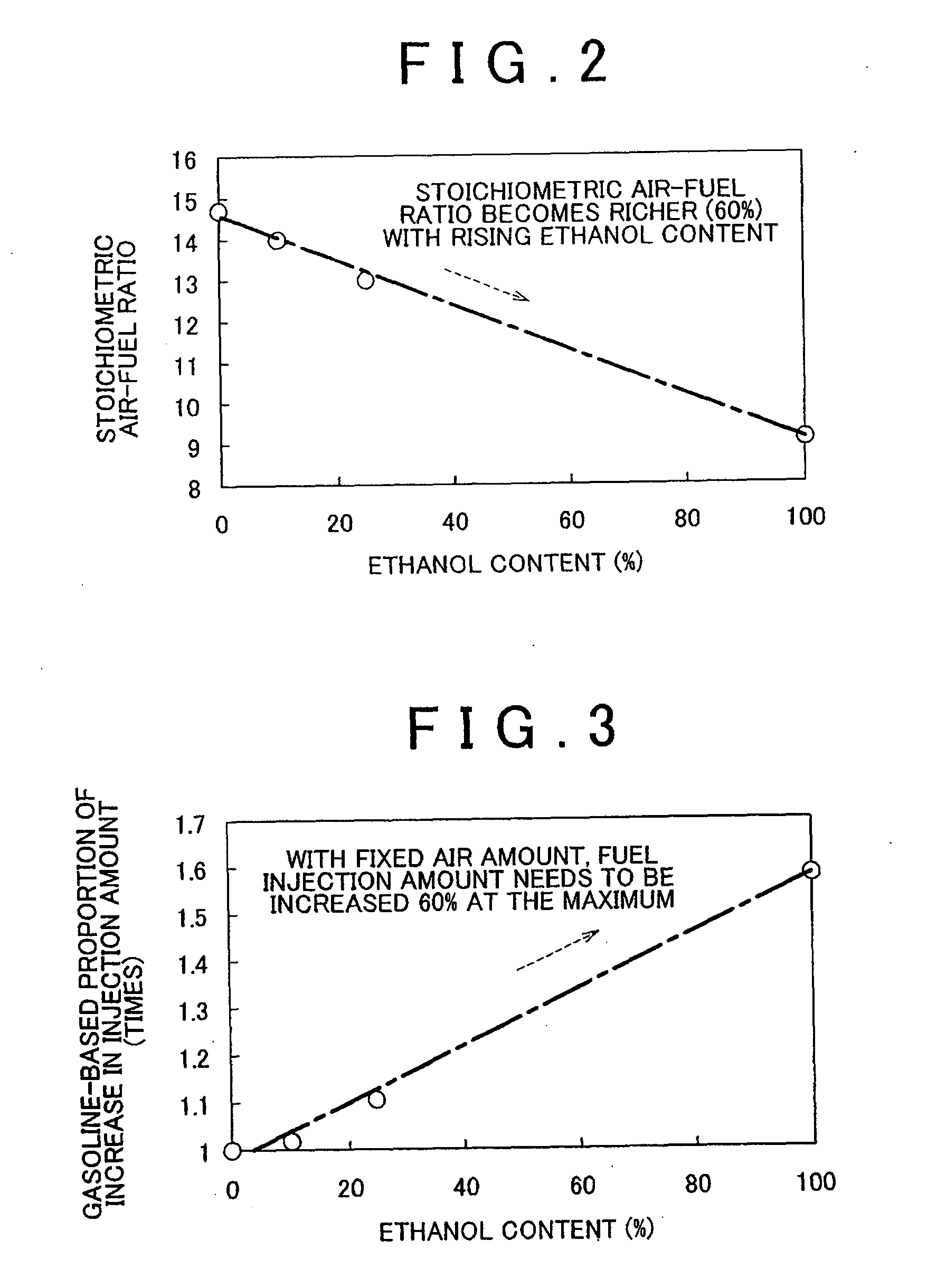
Therefore, in order to truly secure a driveability, it is necessary to suitably adjust the injection amount not only at the time of starting the engine, but also at other times. Furthermore, in a situation where besides gasoline, a blended fuel in which several kinds of fuel, such as alcohol or the like, are blended is used, which trend is recently increasing from the viewpoint of alternative energy, the securement of driveability as mentioned above is becoming increasingly difficult.

Method used


Image

  • Control device and control method for internal combustion engine
  • Control device and control method for internal combustion engine
  • Control device and control method for internal combustion engine

Examples


second embodiment

(2) Second Embodiment

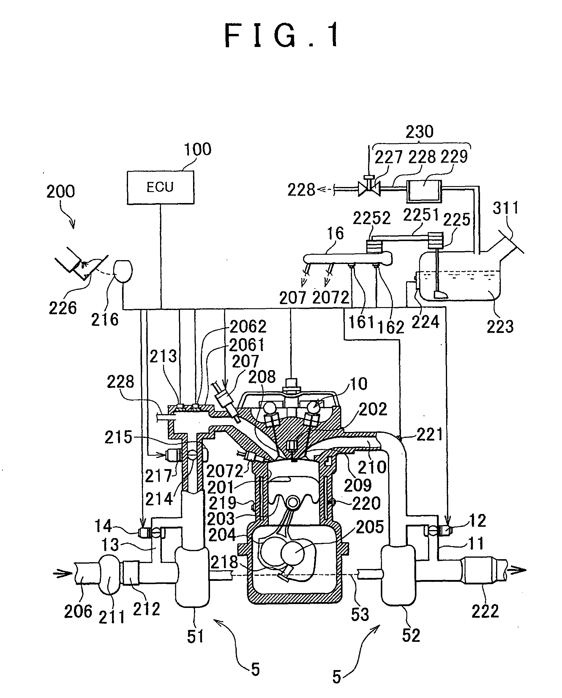
[0107]Operation process of a control device for an internal combustion engine in accordance with a second embodiment will be described with reference to FIGS. 8 and 9 as well as FIGS. 1 to 7. FIG. 8 is a flowchart showing an output correction process in accordance with the second embodiment. FIG. 9 is a characteristic diagram showing a relationship between the target fuel pressure and the limit injection amount. Incidentally, since a basic construction of the second embodiment may be substantially the same as shown in FIG. 1 and the basic operation other than the output correction process may be substantially the same as shown in FIG. 5, the same constructions and steps are assigned with the same reference characters, and detailed descriptions thereof are appropriately omitted.

[0108]According to the second embodiment, even when the intake air amount is restricted as shown in conjunction with the first embodiment, the decline in output can be suitably avoided by ...

third embodiment

(3) Third Embodiment

[0113]Next, operation processes of a control device for an internal combustion engine in accordance with a third embodiment will be described with reference to FIG. 10 as well as FIGS. 1 to 7. FIG. 10 is a flowchart showing an output correction process in accordance with the third embodiment. Incidentally, since a basic construction of the third embodiment may be substantially the same as shown in FIG. 1 and the basic operation other than the output correction process may be substantially the same as shown in FIG. 5, the same constructions and steps are assigned with the same reference characters, and detailed descriptions thereof are appropriately omitted.

[0114]According to the third embodiment, even in the case where a blended fuel is used, it is possible to suitably secure the driveability. Furthermore, because the restriction of the intake air amount is performed via the waste gate valve 12 (or the air bypass valve 14) instead of the throttle valve 214 used i...

fourth embodiment

(4) Fourth Embodiment

[0123]Next, a construction and operation processes of a control device for an internal combustion engine in accordance with a fourth embodiment will be described with reference to FIGS. 11 to 13 as well as FIGS. 1 to 10. FIG. 11 is a characteristic diagram showing a relationship between the engine rotation speed and the torque. FIG. 12 is a throttle opening degree map (at the time of full performance) in the case where the output is made constant by restricting the throttle opening degree. FIG. 13 is a throttle opening degree map (at the time of full performance) in the case where the output is made constant by restricting the supercharge pressure. Incidentally, since a basic construction of the fourth embodiment may be substantially the same as shown in FIG. 1 and the basic operation may be substantially the same as shown in FIG. 6, 8 or 11, the same constructions and steps are assigned with the same reference characters, and detailed descriptions thereof are a...


PUM


Abstract

A control device for an internal combustion engine includes a fuel injection device that injects a fuel in accordance with a required injection amount that is required for combustion in a combustion chamber that is performed to produce an output of the internal combustion engine, and a fuel property specific determination device that specifically determines a fuel property of the fuel injected. The control device further includes a control device that performs an output correction process of controlling at least a portion of the internal combustion engine so as to correct the produced output based on a difference in the specifically determined fuel property. According to the control device and a control method thereof, driveability is secured even in the case where a blended fuel is used during a high load region of the internal combustion engine.

Description

BACKGROUND OF THE INVENTION[0001]1. Field of the Invention[0002]The invention relates to a control device and a control method for an internal combustion engine for controlling an internal combustion engine capable of using a blended fuel in which, for example, several kinds of fuels are blended.[0003]2. Description of the Related Art[0004]Generally, internal combustion engines that use various types of fuels, including internal combustion engines capable of using the aforementioned kind of blended fuel, require a suitable contrivance in order to secure driveability. For example, if the amount of fuel injection is reduced when an idle operation is being performed following the completion of cranking and the engine rotation speed is a low speed, for example, an idling rotation speed, a drop in the engine rotation speed to below the idling rotation speed occurs, and degrades the driveability (e.g., causing a lean misfire, knocking, faults due to an exhaust gas temperature rise, etc.)....

Claims


Application Information

Patent Timeline
IPC IPC(8): F02D43/00
CPCF02B37/00F02D37/02F02D41/0002F02D41/0007F02D41/0025F02D41/40F02D2011/102F02D2200/0611F02D2250/18F02D2250/26F02M25/089F02D19/061F02D19/0628F02D19/084F02D19/088Y02T10/30
Inventor HOKUTO, HIROYUKIMIYASHITA, SHIGEKI
Owner TOYOTA JIDOSHA KK
Learn More