Device for controlling a fluid-activated double-action operating cylinder

Inactive Publication Date: 2009-08-13
ZF FRIEDRICHSHAFEN AG
View PDF8 Cites 25 Cited by
  • Summary
  • Abstract
  • Description
  • Claims
  • Application Information

AI Technical Summary

Benefits of technology

[0010]With a device of this type, the pressure difference between the two cylinder chambers can be determined and, if the geometry of the operating cylinder is known, then so too can be the actual actuation or switching force of the operating cylinder. This information then also enables accurate monitoring and, if necessary, accurate regulation of the switching force.
[0012]Differential pressure sensors are inexpensive structural elements commonly available on the market, so that the arrangement as a whole is not costly.
[0014]In the case of a device, with a pressure fluid line connected to a source of pressurized fluid, which branches upstream from the switching valves into two switching valve supply lines, according to a further feature of the invention, it is provided that the pressure regulation device is a pressure regulation valve arranged upstream from the branching point and actuated by the control unit, such that the fluid supply pressure for the two switching valves and the cylinder chambers downstream from them can be regulated. Such pressure regulation valves are made as pulse-width-modulated, timed, electromagnetic switching values. In this way, the fluid supply pressure for the two cylinder chambers can be controlled, adapted or regulated exactly as a function of the information signal from the differential pressure sensor.

Problems solved by technology

Due to dynamic effects, the compressibility of pressure fluids, the occurrence of dynamic pressures on the outlet side of the operating cylinder, etc., this device is inexact since only the pressure on the inlet side is detected, but not any pressure that may exist on the outlet side.
A further drawback is considered to be that control and regulation processes in which defined pressures must be produced in both cylinder chambers of the operating cylinder, cannot be implemented by the known means.
In this case too a pressure sensor is arranged upstream from a branching point where a pressure fluid line branches off toward two switching valves so that this device suffers from the same disadvantages described in connection with the document mentioned earlier.

Method used


Image

  • Device for controlling a fluid-activated double-action operating cylinder
  • Device for controlling a fluid-activated double-action operating cylinder
  • Device for controlling a fluid-activated double-action operating cylinder

Examples


Embodiment Construction

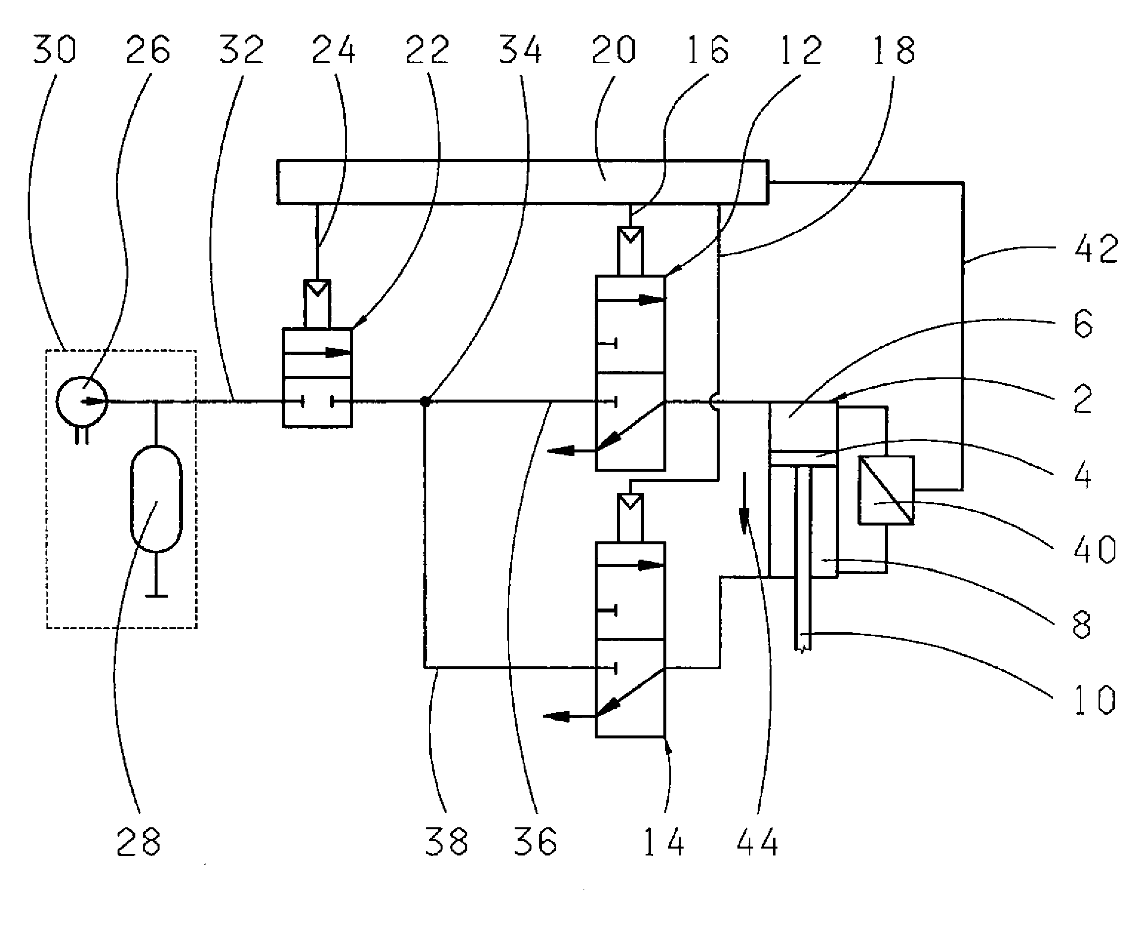
[0019]Accordingly, FIG. 1 shows schematically a device for controlling a fluid-actuated, double-action operating cylinder 2 with two cylinder chambers 6 and 8 separated from one another by a control piston 4. The control piston 4 is connected to a piston rod 10 that passes through an end wall of the cylinder chamber 8 and serves to move a component that has to be displaced in a known manner.

[0020]The first cylinder chamber 6 is associated with a switching valve 12 made as a 3 / 2-way electromagnetic valve, which controls the flow of fluid in and out of the cylinder chamber 6 and the cutting off of this cylinder chamber from the inflow or outflow. The second cylinder chamber 8 is associated with a switching valve 14 of the same type. The switching valves 12 and 14 are connected by respective associated control lines 16 and 18 to a control unit 20.

[0021]Connected upstream from the two switching valves 12 and 14 is a controllable pressure regulation device 22, which is also connected by ...


PUM


Abstract

A device for controlling a fluid-actuated, double-action operating cylinder (2) having two cylinder chambers (6, 8) separated from one another by a piston (4). Each cylinder chamber (6, 8) communicates with a respective valve (12, 14) for controlling the flow of fluid in and out of the cylinder chamber (6, 8) and a pressure sensor (40) for detecting the fluid supply pressure. A control unit (20) is connected to the switching valves (12, 14) and the pressure sensor (40). To determine the actual control force of the operating cylinder (2), the pressure sensor (40) is arranged between the cylinder chambers (6, 8) and the control unit (20). The output from the pressure sensor (40) can be processed in the control unit (20) and used for actuating a pressure regulation valve (22) arranged in the pressure line (32).

Description

[0001]This application is a national stage completion of PCT / EP2007 / 055570 filed Jun. 6, 2007, which claims priority from German Application Serial No. 10 2006 030 034.3 filed Jun. 29, 2006.FIELD OF THE INVENTION[0002]The invention concerns a device for controlling a fluid-actuated, double-action operating cylinder.BACKGROUND OF THE INVENTION[0003]Fluid-actuated, double-action operating cylinders are used as operating drives for automated transmissions or clutches in motor vehicles and can be part of a pneumatic or a hydraulic system. As is known, the piston of a double-action operating cylinder can move in two directions. In general, the fluid inflow or fluid outflow for the cylinder chambers of an operating cylinder or the blocking of the chambers to prevent inflow or outflow are controlled by switching valves connected to the control unit. In addition, a pressure sensor device is often provided upstream from the operating cylinder in a pressure medium liner which detects the flui...

Claims


Application Information

Patent Timeline
IPC IPC(8): F16H31/00
CPCF15B11/028F16H2059/683F15B11/044F15B2211/455F15B2211/46F15B2211/513F15B2211/527F15B2211/565F15B2211/6313F15B2211/7053F16H61/0021F16H61/2807F16H61/30F16H2059/6807F15B11/042
Inventor PETZOLD, RAINERMULLER, BERNDWOLFGANG, WERNERJAGER, THOMASSTEINBORN, MARIOREITH, ULRICHHERTER, PETERMAIR, ROLAND
Owner ZF FRIEDRICHSHAFEN AG
Why Eureka
Try Eureka