
Electronic device and lc shutter for polarization-sensitive switching between transparent and diffusive states

a technology of polarization-sensitive switching and electronic devices, applied in non-linear optics, instruments, optics, etc., can solve the problems of not enabling embodiment cannot achieve the effect of switching and not enabling between a transparent and a diffusive sta

Active Publication Date: 2009-08-13
GOOGLE TECH HLDG LLC
View PDF93 Cites 3 Cited by
  • Summary
  • Abstract
  • Description
  • Claims
  • Application Information

AI Technical Summary

Problems solved by technology

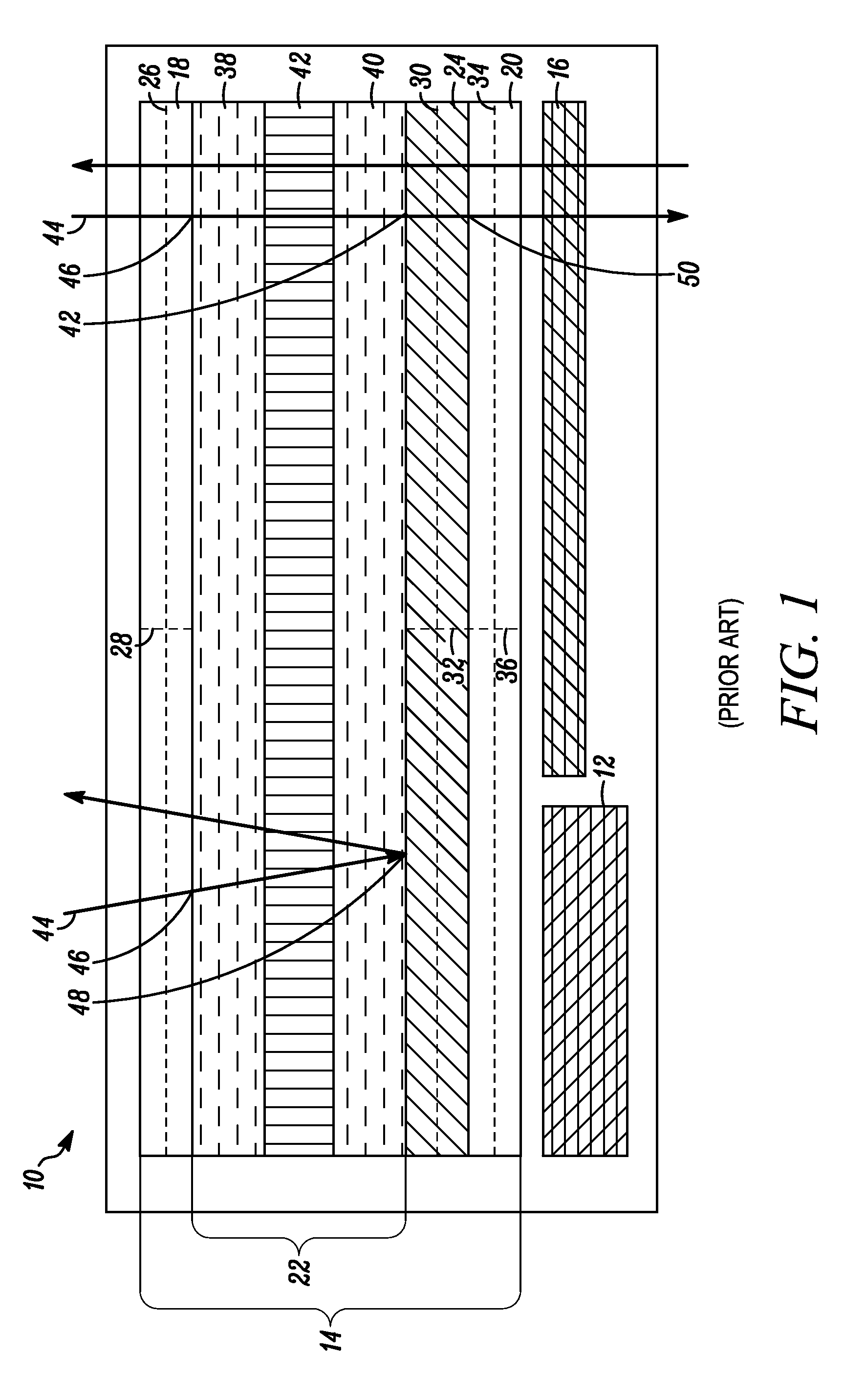
One embodiment of the '044 patent also employs a diffusive adhesive to achieve diffusive colors, but this embodiment cannot achieve switching between a transparent state and a diffusive state because as long as the diffusive adhesive is present, all incoming light is diffused under all circumstances.
Because the light scattering layer is not polarization-sensitive, however, this construction does not enable switching between a transparent state and a diffusive state.
The scattering layers are not polarization-sensitive and thus do not enable switching between a transparent and a diffusive state.
This construction is also cumbersome because it uses two LC cells in the LC shutter.
Such absorption of “wrongly-polarized” light is wasteful.
Thus, if a diffusive reflective polarizer is used in such a construction, it only provides “recycling” capability and does not enable the LC shutter to switch between a transparent state and a diffusive state.
Other constructions do provide for switching between a transparent state and a diffusive state, but are not polarization-sensitive LC shutters and therefore produce lower image integrity, along with lower transmission in the transparent state.

Method used


Image

  • Electronic device and lc shutter for polarization-sensitive switching between transparent and diffusive states
  • Electronic device and lc shutter for polarization-sensitive switching between transparent and diffusive states
  • Electronic device and lc shutter for polarization-sensitive switching between transparent and diffusive states

Examples


Embodiment Construction

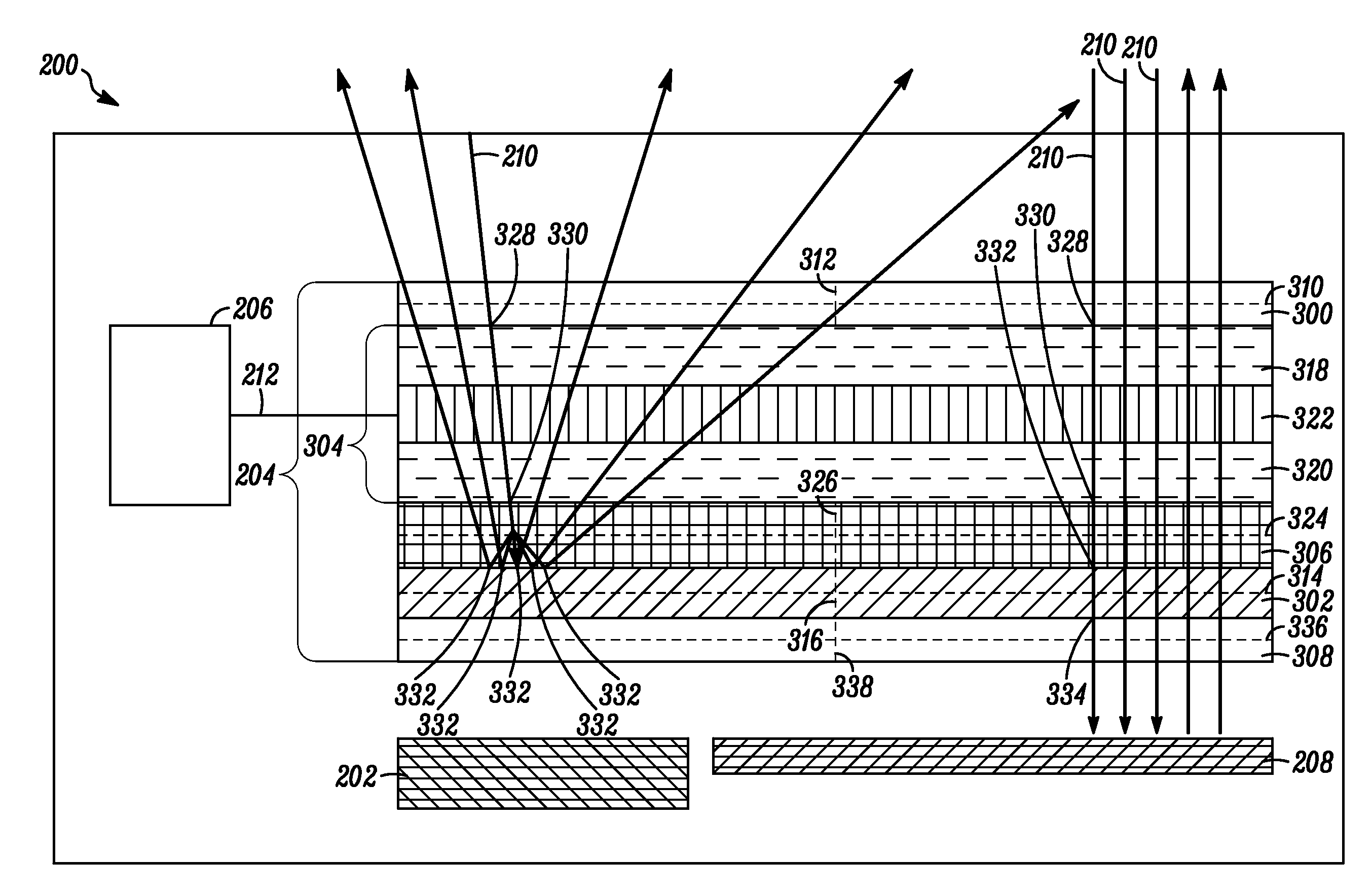
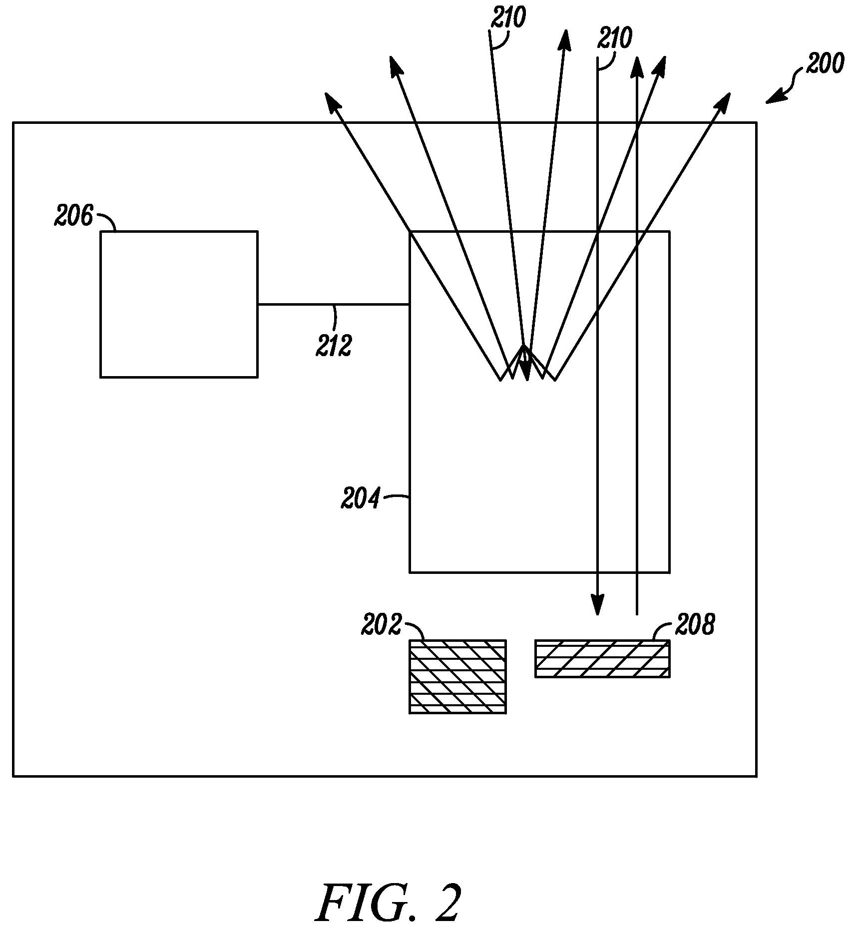
[0020]Briefly, an electronic device includes a display and an LC shutter. At least a portion of the LC shutter is operatively positioned over the display. In one example, the LC shutter provides switching between a diffusive state and a transparent state with high image integrity, and with high transmission in the transparent state. The diffusive state can be controlled to be a diffusive white state or a diffusive colored state, such as through the selective placement of a narrowband dichroic polarizer or narrowband reflective polarizer within the LC shutter to introduce color. In one embodiment, the electronic device further includes control logic operatively coupled to the LC shutter and operative to provide control signals to the LC shutter to effect the transparent state. When the control logic does not provide control signals to the LC shutter, the LC shutter operates in the diffusive state. The LC shutter includes a first dichroic polarizer, such as a broadband dichroic polari...


PUM

PropertyMeasurementUnit
anisotropicaaaaaaaaaa
refractive indexaaaaaaaaaa
timeaaaaaaaaaa

Abstract

An electronic device (200) includes a display (202) and an LC shutter (204), at least a portion of which is operatively positioned over the display (202). The LC shutter (204) provides switching between a transparent state and a diffusive state with high image integrity, and high transmission in the transparent state. In one embodiment, the electronic device (200) further includes control logic (206) operatively coupled to the LC shutter (204) to provide control signals (212) to the LC shutter (204) to effect the transparent state. The LC shutter (204) includes a first dichroic polarizer (300), such as a broadband dichroic polarizer, a specular reflective polarizer (302), such as a broadband reflective polarizer, an LC cell (304), and a diffusive reflective polarizer (306). The LC cell (304) is interposed between the first dichroic polarizer (300) and the specular reflective polarizer (302). The diffusive reflective polarizer (306) is interposed between the LC cell (304) and the specular reflective polarizer (302). Related methods are also set forth.

Description

RELATED APPLICATIONS[0001]This application is related to co-pending application entitled “ELECTRONIC DEVICE AND LC SHUTTER WITH DIFFUSIVE REFLECTIVE POLARIZER”, filed on even date, having docket number 33692.07.5334, inventors Zhuang et al., owned by instant Assignee and is incorporated herein by reference.FIELD OF THE INVENTION[0002]The present invention generally relates to electronic devices that employ liquid crystal shutters.BACKGROUND OF THE INVENTION[0003]Image morphing capability is increasingly becoming an important design consideration in electronic devices. In the optical and imaging arts, “morphing” refers to the changing of one image to another. For example, electronic devices frequently employ “morphing user interfaces,” i.e., interfaces that change in appearance as a device's use changes. Such an interface is simpler and more intuitive to use since only the context-relevant functions are shown at any given time, with the interface elements that are not related to the ...

Claims


Application Information

Patent Timeline
Patent Type & Authority Applications(United States)
IPC IPC(8): G02F1/1335
CPCG02F1/133528G02F2001/133626G02F1/1336G02F1/133536G02F1/133626
Inventor ZHUANG, JIMISHIKAWA, TOMOHIROPOLAK, ROBERT
Owner GOOGLE TECH HLDG LLC
Learn More